BACK TO: HOME
FORWARD TO: INITIAL PHYSICS
Contact me: John@SnellsNotebook.us - Last Updated: 23 NOVEMBER 2020
BACK TO HOME
I started out to simply try to find the most accurate load for my rifle. At the time, all of the published information said to just keep trying different powder charges, bullets and primers. Although I looked in many reloading manuals, and read ever periodical I could find, I was unable to learn of any methodical way to adjust loads to produce accuracy. I did however find a tremendous amount of non-sense, circular logic, and flowery words without meaning. As the result, I started to research the topic on the Internet. Eventually, between some very old periodical articles, and some very new Internet postings, I was able to assemble a fact based logical approach to economic load development of accurate (small group) ammunition.
As the information began to accumulate, I found myself interested in publishing my findings so that the next hand loader could find and benefit from my research.
Of course, many other topics came up, and questions were asked. So I decided to compile what I know and what I believe to be true into an indexed web page.
What follows is the result.
I have found that a short concise list of safety rules is much
easier to teach, learn, and use.
The immortal Col. Jeff Cooper
posited four simple rules that I believe are sufficient for all
cases.
Rule 1: All guns are loaded at all times.
Rule 2: Never point a gun at anything you don't want to destroy.
Rule 3: Keep your finger off the trigger until you are ready to shoot.
Rule 4: Be certain of your target and beyond.
If you always do these four things you will never be the cause of
a shooting accident.
Lets look a little closer at the rules to
see how they are applied in daily use.
Obviously that can not be true all of the time, but if you TREAT
all guns as if they are loaded at all times you will never point a
firearm you 'thought was unloaded' at something you didn't want to
destroy.
You should never hand another person a gun that you
have not personally inspected (cleared), and you should under most
conditions open the action, and confirm that the gun is unloaded
before you pass control of it to another.
To clear a gun you
open the chamber, (where the bullets go to be fired), and inspect
the
gun to ensure there is no ammunition in the chamber. Further, with
regard to repeating arms you should also inspect the magazine,
(where
the bullets are carried before they are loaded into the chamber),
to
ensure there are is no ammunition waiting to be loaded.
A
cleared gun is one that has been inspected to ensure there is no
ammunition loaded or waiting to be loaded.
The exceptions to
rule one, that I can think of at the moment are:
If you are teaching someone to shoot, you may load the gun for them, put the gun on safe and hand it to them. This should be done so that the student has a full and complete view and explanation of how the gun is loaded, and what additional steps are necessary to make the gun ready to fire. This activity should be conducted on the range, and the instructor is responsible for ensuring safe range operation.
If you are in a situation where you must use a gun for self defense, or where you must provide a gun to someone for self defense immediately, it would not be unreasonable to pass a loaded firearm from one to another. The firearm safety should be engaged prior to passing the weapon. This is an inherently risky operation, and should be anticipated in training.
These are NOT exceptions:
Crossing a fence. If you hand your gun to another person during a maneuver, for example; crossing a fence, the gun should be unloaded, cleared and then handed to the other party. The gun(s) should stay unloaded until everyone has passed the obstacle. In point of fact, hunting guns should stay unloaded until the hunt has progressed to the point where the action of loading might cause game to learn of your presence.
Casually handing a firearm to another. This is a major source of accidents! Always unload before transferring. Always check for yourself when receiving.
It seems pretty simple. With practice it can be, but without
constant vigilance it is very easy to 'cover' ie 'point at' other
people in your vicinity. For example if you are hunting, and
carrying
your rifle in two hands, you must be aware when turning that your
muzzle does not 'sweep', 'cover' or 'point at' any person or thing
that you don't want to destroy.
Pointing your muzzle up, down,
or to the side is acceptable. If your gun should accidentally
discharge with the muzzle pointed straight up, your bullet may not
have killing power when it returns to earth.
Mythbusters did
a very thorough analysis of the subject and found that a bullet
fired
straight up lost gyroscopic stability near the top of its flight,
and
then fell to earth sideways. While the returning bullet might hurt
if
it hit your head, it would not contain sufficient velocity and
stability to penetrate deeply. However, if a gun is fired on any
angle other than straight up there is a likelihood that the bullet
will retain gyroscopic stability and velocity sufficient to case
damage or death upon return to earth. The danger range for such is
on
the order of 3 miles.
If you point your muzzle down and the
gun discharges, your bullet may be absorbed by the earth at your
feet. (assuming you didn't shoot yourself in the foot), or it may
encounter rocks which may cause the bullet to break up and
'splash'
in all directions (your legs are closest!). If your gun is pointed
some distance away and down, the bullet could ricochet (bounce)
and
travel miles before loosing lethal energy.
The military has
found that on those occasions when carry a loaded weapon inside a
vehicle is appropriate, that pointing the muzzle down is generally
the best solution. In helicopters and automobiles bullets fired
down
will do the least damage.
For non-combat applications,
keeping your weapon unloaded until just before firing is the best
way
to ensure that whatever you may point at is not likely to be
destroyed.
For combat applications (daily CCW carry, armed
response to attackers etc.) you must train often to ensure that
your
muzzle discipline is as near perfect as possible. This involves
training with everyone who may be involved with the operation e.g.
family members etc.
If you draw a pistol from its holster or
place of concealment you might point it at yourself or others. A
right handed shooter drawing from a right side holster using a
conventional muzzle down, butt to the rear carry at the hip, will
only point his or her muzzle down, then rotate vertically to the
target. A shooter using a cross-draw (gun is on the side opposite
the
firing hand) likely will point the muzzle in an arc that may sweep
across any person to the shooter's weak (non-firing) side and/or
front. A shooter using a back of the spine holster may point at
themselves around the hips and legs, and must make an effort in
training to control where the muzzle points, as it is all too easy
to
raise the muzzle early and sweep yourself on the strong side, or
anyone to your stong side. A person using an appendix carry (in
front
of the hip) is very likely to point the muzzle at their own body
during a draw, and must be careful to not sweep to the weak side.
A
person utilizing off-body carry, for example a purse, typically
has
the same problem as a shooter using a shoulder holster or a cross
draw holster. These are the reasons for Rule 3.
To ensure you
are safe drawing your weapon, practice in front of a mirror while
drawing slowly and deliberately. Observe the path of the muzzle.
As
you gain skill, increase your draw speed, and continue to observe
the
muzzle until you are confidant that no outside force applied
during
your draw can cause unintended mayhem.
As you may have imagined if you followed the discussion about rule 2, there are times when your gun may be pointed somewhere you didn't really want to point it. As long as the guns safety is on, and the trigger can not be pulled inadvertently, there is still a safety margin during these events. Some modern firearms have only one safety mechanism - a small blade within the trigger that only unlocks when a finger (or something like a finger) is pressing on the trigger. Other firearms have additional safety mechanisms. To my knowledge the venerable 1911 semi-automatic pistol has the most at six separate safety mechanisms.
Modern striker fired pistols based on principles similar to the GLOCK series have these features:
1. Trigger Blade. If the trigger blade is not depressed, the trigger can not fire the gun.
2. Trigger disconnector (same as 1911 above).
On some modern pistols there is a 'magazine disconnector' which is designed to prevent the gun from firing if the magazine is removed. The theory is that as a last resort you could eject the magazine before the weapon leaves your control. Perhaps moderately useful during storage to prevent children from activating unsecured guns, while permitting quick action by only inserting a magazine. In most cases a magazine disconnector is a death trap waiting to be sprung on the shooter who has one round in the chamber and is the midst of reloading. That round CAN NOT BE FIRED until the magazine is fully inserted, and MIGHT be fired inadvertently if the trigger is being pulled while the magazine is inserted. Firearms having magazine disconnectors require additional extensive training to avoid all the problems they create.
3. Loaded chamber indicator. This is usually the extractor which is designed so that when a case is present in the chamber it rests proud of the surface. It is always tactile, and sometimes visual.
4. Manual safety. On some striker fired pistols the manufacturer has included a manual safety that typically operates similar to the 1911. When not present, and a DA/SA trigger is in use, the decocker may be present. It's purpose is to relax the main spring by lowering the hammer against a stop that prevents the hammer from reaching the firing pin.
5. Trigger Guard.
Some semi-automatic pistols rely on a heavy and/or long trigger pull to prevent accidental discharge. These are sometimes referred to as DA/SA (Double Action / Single Action) triggers.
DA pistols (as opposed to revolvers) featuring a long heavy first shot trigger pull, followed by much lighter subsequent trigger pulls are not my favorites. The second shot followup is always going off before the sight picture is correct (because the trigger is so much lighter than it was a split second ago), and typically these pistols require a 'decocking' mechanism, to return to a safe (and long heavy trigger pull). I find the decocker to be one of the most 'evil' inventions, right up there with magazine disconnectors! It is just plain wrong to allow a hammer to fall when not either firing, or dry firing. I can not make myself 'believe' in the safety of the mechanism, and I don't like the abrupt stop the hammer experiences because this is the road to fatigued metal. In any case, if you own one of the pistols with this feature (Walther PPK, S&W, etc.) please train yourself and remember all the rules of firearms safety apply at all times, so NEVER EVER operate a decocker with the muzzle pointed in an unsafe direction. Always get your finger off the trigger and out of the trigger guard before decocking any of these style pistols.
Modern revolver safeties generally consist of the following: Bars that must be moved into position between the hammer and the firing pin by action of the trigger to allow transfer of the hammer energy to the firing pin. Firing pins that do not have the mass to detonate a primer no matter how hard the revolver may fall, and various mechanisms to ensure the alignment of the chamber with the barrel at the moment of firing. They are strong guns with substantial frames made from high strength materials and can withstand much higher operating pressure than older revolvers.
Antique revolvers safeties generally consist of making sure you don't carry a live round in the chamber that is under the hammer. This is accomplished by loading one round, skipping one round, and loading 4 more rounds in sequence, then cocking and lowering the hammer on the empty chamber. Its a skill you should develop early in your training on an antique revolver like the Colt SSA. Failure to abide by the rule to keep an empty chamber will (not may) cause the gun to fire when the hammer is struck. Immediately unload or reload the revolver and make sure the hammer rests on an empty chamber after firing. Simply easing the hammer down, or using the half cock notch will result in undesirable conditions.
Revolvers come in two types, single action, where the hammer is cocked manually for each shot, and double action, where the trigger can be used to cock and fire the revolver in one continuous motion. Modern double action revolvers invariably possess single action capability in addition.
As you can see, a lot of thought has gone into making guns safe. A safe gun is one that will not discharge inadvertently, but will fire instantly when the operator so chooses. The trigger is the final safety. To defeat the final safety only requires some amount of pull and the gun will fire if it can. If you put your finger into the trigger guard, you have provided a means for external forces (think the side of your holster, or an opponent) to mimic pulling the trigger. Keeping your finger (and everything else) out of the trigger guard area eliminates the threat that the gun can fire due to negligent handling. In particular keep your finger off the trigger AFTER you have ceased firing and MOST ESPECIALLY, keep your finger off the trigger when re-holstering your gun. Train yourself by performing slow draw, aim, fire and re-holster drills. With an unloaded gun, watch what happens if your trigger finger stays in the trigger guard. Some holster designs will cause you to press the trigger. Know your equipment. Always train the way you want to fight.
Do not shoot at things you can not positively identify. A very large percentage of accidental shootings happen because the shooter does not take time to positively identify the target before firing. Know you are shooting at the correct target, and conversely know that if you bullet penetrates your target it will not damage anything around or beyond the target. For example if you are hunting and a shot at a great trophy appears on the crest of a hill, you should wait until the animal moves off the crest of the hill, so that a hit or a miss will land where you know the background. Shooting over hills, and across bodies of water, and along or across roads have been responsible for many firearms accidents. There is one time, and only one time when you shouldn't spend too much time worrying about the background, or where your bullet may go, and that is when you are forced to fire on another human. In that one case, most courts have held that any damage resulting from a justified shooting is the fault of the perpetrator rather than the victim. This is the result of the notion that all the results of a bad deed are the fault of the one committing the bad deed. You should of course be aware of your immediate surroundings, and if possible move to ensure you do not shoot into say an adjacent bedroom where you know someone to be sleeping, but in the event your are forced to fire, then fire for effect. The good news is that in your home you can plan ahead to know where safe shooting lanes are located, and you can plan ahead to use equipment and ammunition that is suited for your circumstances.
Marksmanship is the art and science of firing a hand held or shoulder fired gun.
Competition marksmen live in a world of rules. Their shooting position(s) are dictated by the rules for the discipline or the match. NRA Smallbore and High Power marksmen have prone, sitting, kneeling and standing positions to master at the same time they skill with their hardware. Tactical marksmen must master shooting from sometimes difficult positions while being able to utilize a wide range of support options. Hunters pretty much have no rules about positions, but will find that prone, sitting and standing as well as using whatever support is available are the options.
Beginners would do well to master the conventional match positions of prone, sitting, and standing first. Then master shooting from a shooting bench, and perhaps last make an effort to use kneeling until you are comfortable and accurate in that position.
Natural Point of Aim - When you have completed getting into position to shoot, close your eyes, relax all of your muscles. Count to 5. Open your eyes and check to see where the rifle is pointed. If it is not pointed directly at the place where you want the bullet to strike, adjust your position and repeat. Whey you have found your natural point of aim, you should be able to remain in that position for an extended period of time and you should not have to 'muscle' the gun to get onto or stay on the target.
Prone is considered to be the most stable position. I have found that shooting from a bench is much more stable, repeatable, comfortable, and produces much higher accuracy for most people. Bench technique is a lot more than just sit down and bang away. Lets cover some of the basics for each position:
Prone will get you out of the line of incoming fire as much as possible, allow you to sneak up on targets, and crawl around below the top of the brush etc.
Prone With Sling - In this position the shooter lays flat on their stomach, pelvis and ankles. Elbows and shoulder support the rifle. A sling connected to the front of the rifle's stock and wrapped around the 'support side' (opposite of the trigger finger) forearm and upper arm, may or may not be connected to the butt of the rifle. Properly adjusted the sling will allow the support side hand's grip to control elevation with little effort as it slides back and forth along the forend. Shooters body should align just slightly to the support side as viewed from above. The sling should be tight, and the butt of the rifle should be tight against the shoulder. Follow through the shot by riding the recoil with the rifle.
Prone with Support - In this position the shooter will be more directly in line with the rifle, and the support side arm will not be involved in supporting the rifle, as it is supported by something (bipod, backpack, etc.). The support hand can either help control the vertical by supporting the butt, or help stabilize the rifle by ensuring it doesn't fall off the support. The support hand should be available to make sight corrections (dial up the scope), or adjust parallax (on a modern long range scope). The support side hand should not in any way support the gun forward of the butt. Follow through the shot by ensuring the rifle recoils straight back into your shoulder. You may support the butt of the rifle with a bag or a mono-pod.
Sitting will get your line of sight above the grass (most of the time), allows you a little bit of lateral (tracking) movement, may offer a position you can remain in for long periods comfortably.
Sitting With Sling - Cross your legs at the ankles, or place your feet slightly apart. This position changes quite a lot based on foot position choice. In competition crossing ankles, and leaning far forward so your elbows are outside your knees is typical, and makes this position even more stable for me than prone. The open sitting position is much more suitable for hunting or tactical applications where movement is necessary. In the 'closed' position the rifle sling is employed the same way as in prone, and the rifle is held tightly to the shoulder. Follow through by ridding the rifle's recoil. In the 'open' version of this position, the elbows are placed to force the knees apart. If you have a spare rope or belt, to constrain the movement of your knees this can be a long term comfortable position. In the open version of sitting follow through is again a tight sling and riding the rifle's recoil.
Sitting With Support - This position can become difficult if you loose flexibility in your core (eg get fat), because in order for it to work well, you need to lean into the rifle and you don't have the luxury of the rifle's weight, or a sling to help with that movement. Essentially you will be in a 'kip' position, and muscle strain (bad for shooting accurately) will start immediately. Generally sitting with sling is more stable, unless terrain offers support for the shooter. There is also a 'high sitting with support' (long bipod, tripod, shooting sticks etc.) position that may include a short chair, or kneeling with both knees on the ground, while your weight rests on your heels. Follow though in these supported positions may be best if you utilize 'free recoil' - in other words, your body does not resist the recoil, and does not support the rifle. When the rifle recoils, it does so free of obstruction (for a few inches). It does not take much distance between the butt pad and the shoulder to create a free-recoil setup, however in that distance the rifle is free to accelerate and with heavy recoiling calibers that may be enough to cause problems. In free recoil you firing hand should be setup in such a way that it does not influence recoil. Many shooters put their thumb on the back of the trigger guard, and their trigger finger on the trigger, and have no other contact with the rifle. You should work up to free-recoil, its a good way to get a scope cut, drop your rifle, dislocate your shoulder, etc. Be sure you know what's going to happen. Heavy (12-13 lb) low recoil rifles (308 Winchester and below) generally have a low enough recoil impulse that free-recoil is practical and you can learn it with little risk. Don't start off with a 6 lb 7mm Magnum!
Kneeling raises your line of sight above what you had in most sitting positions. It also allows for rapidly assuming the position, and rapidly resuming stalking, or tactical movement with a minimum of noise and visual signature. The accuracy potential from kneeling is probably twice to three times better than from standing unsupported (offhand).
Kneeling With Sling - Once again a tight sling can increase your stability significantly in this position. Your support side foot should be flat on the ground, your shin straight up, your knee bent. The support side elbow should be just over the knee. The trigger finger side elbow can be down, but if you shoot a heavy recoiling rifle, putting that elbow parallel to the ground will open your shoulder pocket and allow absorbing much more recoil. Follow through in kneeling with a sling, as before, to have tight sling, and ride the rile throughout the recoil pulse.
Kneeling With Support - Generally this position only happens if you have to work from under some obstruction. Typically any shot you would take from this position can just as easily be taken from standing with support, and with about the same accuracy.
Standing, also known as 'offhand' is the most challenging position to shoot accurately from. In this position a sling is generally a detriment to accuracy. Since most hunting and tactical rifles will have a sling attached part of your training for this position will be to secure the sling so that it does not impart movement.
Standing Unsupported - In this position you will not be able to hold your sight picture for any more than a few seconds. There are at least two ways to address this problem with technique. First what I call the 'shotgun approach' which works well for quick shots on larger targets. Mount the rifle so that the sights are in the correct position instantly. Your eyes should be looking at and focused on the target as you mount the rifle. The moment the rifle is mounted, you should be able to pickup the sights. If you try to stand still you will wobble around in circles (we'll talk about that next). To keep from wobbling around you will need to muscle your gun in such a way that the sight track across the aiming point (AP). If you move too quickly this won't work as well as if you move slowly and deliberately. The amount of movement is very small, maybe not more than 2-3 MOA (Minutes Of Angle). As you push your sights across the AP coordinate your trigger finger to break the shot just before your sights reach perfect alignment. This movement is very similar to the way a shotgun is fired. It takes practice to achieve high accuracy, but once you get the hang of it, you can take on difficult targets at high speed, with a great deal of success. The reason it works, has to do with how your muscles don't want to hold still as much as they want to move. You can apply a very smooth movement across the target, but you can't hold very still on target.
Standing Supported - In this position you will be erect behind shooting sticks, tripod, or rested against a support (tree, door frame etc.). Your rifle will be constrained at the point where the support occurs. If you choose to put the support near the balance point of the rifle, it will be easy for you to move up and down. If you put the support nearer the muzzle, you will have to make gross movements to change your point of aim, and those movements will by necessity be made by your entire body, or by repositioning the support. This position will feel very un-natural until you have practiced it a lot. It will also take quite a while for you to determine the correct length for adjustable legs, and position (fore and aft) on the rifle. One trick to really 'clean up' this position is to back into a tree or other stable support. You won't believe how much your upper body wants to move around until you constrain that movement. In standing supported you may find the sights are wandering all over the place just like standing unsupported, but if you watch closely, you'll see that they tend to oscillate in a typically circular pattern. By watching the pattern, you can predict when the sights will approach the AP. If you have excellent trigger control, you would take up 3/4 of the trigger weight as soon as your sights are close to the AP. Hold that. When your sights come around on their oscillation, take some of the remainder as the sights approach the AP, and hold as the sights depart. Continue this until you have what Col. Jeff Cooper called a 'surprise break'. This trigger technique is valid for all positions, at all times, but you will get the best training opportunity in Standing Supported.
A word about follow through; The ideal situation is for you to have zero reaction with the shot breaks. Be like a bag of sand, just absorb the recoil, hold the trigger, and DO NOT BLINK. That last one is perhaps the single hardest thing to do for most people. You will have to convince your subconscious first to delay the blink, then since 'nothing ever happens' to do away with the blink completely. Blinking is a reaction to an unexpected event typically recoil, or sound, or for scoped rifles, the loss of sight picture. Blinking will prevent you from seeing where your shot impacted, which will prevent you from making a correction if necessary. One technique I've used to overcome blinking is to become so engrossed in watching the scene unfold after a shot, pickup the trace, see the 'glint' from the bullet, watch for impact, etc. that I actually don't blink. It takes a while (unless you shoot tracers - that's a real shortcut!) until you can stall the blink response long enough to see anything of interest, then all of a sudden you will 'get over it' and be able to watch everything. Once you have that mastered, you can work on getting recoil to push your rifle straight back, and returning the rifle to 'battery' all during bullet flight time. If you want to work up in stages, I recommend you start by learning to hold your trigger all the way through the shot.
You will hear instructors mention 'The Fundamentals Of Marksmanship' very often. Mastery of the fundamentals is key to shooting accurately. So what are these fundamentals?
According to the US Army these are four fundamentals of Marksmanship:
Steady Position
Aiming
Breath Control
Trigger Squeeze
This is a link to the US Army Study Guide
The Washington State Criminal Justice Training Commission Patrol Rifle Course added the following:
Grip
Stance
Breathing
Sight Alignment
Sight Picture
Trigger Manipulation
Follow Through
This is a link to the document
Another US Army guide is much more simple:
Properly point the rifle at the target
Fire the rifle without moving it
This is a link to the web page, there are some very good graphics on this one.
Establish a solid shooting position.
Do not allow the barrel to come into contact with anything.
Front rest should be close to the front end of the stock, leaving sufficient room for recoil.
Rear rest should be close to the rear of the stock. Observe that the rear rest allows for 2-3 inches of rifle movement during recoil.
Position yourself behind the rifle so that your head on the stock is close to the same position as if you were standing. Often this can be accomplished by changing your seating height. One of the reasons I recommend a Drummer's Throne type of stool for bench shooting.
Position your right hand to lightly grasp the rifle and reach the trigger with the middle of the pad on the tip of your index finger.
Position your left hand to either operate the forward rest controls (elevation and windage), and/or squeeze and steer the rear bag. If your hand is near the rear bag when you shoot, make sure it is out of the area where the stock can hit it during recoil.
You should seat the rifle into your shoulder with no gap. If you leave a gap with a high recoiling rifle it will cause more discomfort. Do not pull the rifle hard into your shoulder, unless you can pull it the exact same way repeatedly. Try not to change the recoil dynamics.
Use tripod shooting sticks to support the front of your rifle for positions from prone to standing. There are short tripods for prone and taller much more adjustable tripods for everything else.
Use bipod shooting sticks when weight is an issue.
Use a stock mounted bipod when shooting from prone to sitting. Learn to pre-load the bipod so that the rifle will recoil naturally.
To pre-load a bipod; as the last step in building your natural point of aim shooting position, press your shoulder forward just enough to rock the bipod to it's forward limit of travel (which may be very small). Don't press hard enough to skid the feet. Ideally, at the moment of recoil, the bipod will rotate backward, and your shoulder will stop the recoil motion before the bipod feet skid in recoil. The idea is to enable the bipod to have the range of motion necessary to allow the rifle to recoil without the bipod feet moving.
Arrange so that the bipod legs can not move forward from the firing position
Press forward using only your shoulder on the butt of the stock until all slack is just removed from the bipod legs.
Under recoil the legs should allow the rifle to recoil in a straight line into your shoulder.
Use a backpack if nothing else is available.
Use a rear mounted monpod to support the rear of the rifle when possible.
This is the most stable position. For practical applications, this position is best used with a rest at both the forend and the toe of the stock. These rests may be tripod, bipod, or monopod devices, or bags designed for this purpose, or a field expedient rest composed of pack, jacket, rocks, logs, etc.
The forward rest should be located as far forward as is practical to reduce motion as much as possible.
The rear rest should be located under the toe (bottom) of the stock as far to the rear as is practical. The rear rest should be able to be adjusted by the shooters weak side hand to control elevation.
The rifle should be supported so that in recoil it moves directly to the rear.
The shooter should be positioned straight behind the rifle to absorb the recoil in a straight line. This promotes rapid return to the natural point of aim, which should also allow rapid re-engagement of the target.
For traditional match shooting where no rests are allowed, the shooter should use a sling (strap) to apply tension between the weak side upper arm and the sling swivel at the front of the stock. The sling shold wrap around the shooters arm, and have just the length to allow a tight position. In this position, the shooter should be aligned at an angle to the rifle so the weak side can support the rifle sling and create a triangular structure for support.
Learn to use a sling to steady the rifle. As mentioned above, a sling is not desirable for a fully supported prone position, however it does become useful for practical sitting, kneeling and squatting positions. Practical rile shooters should make a habit of constructing solid shooting positions with and without the use of a sling. For practical and hunting positions, creative use of the sling will add safety and support to the rifle system
Learn to avoid transmitting your brachial pulse to the sling.
In traditional match shooting shooters had to contend with their pulse being transmitted to the rifle system by way of the sling. The primary culprit is the brachial artery in the upper arm. The pulse effect can be mitigated by placing the sling above or below the center of the arm, and by padding at the source of motion.
Use a sling for stability.
Learn to shoot both cross legged and open legged.
Cross legged, place elbows over your knees, hook yourself into the position
Open legged place elbows into the 'pockets' of your knees and push out. For practical shooting, you can use a belt or rope to hold your knees together to significantly stabilize open legged sitting.
Use a sling for stability. Learn to place your weak side elbow over your week side knee.
A sling will only slightly improve stability in this position, and requires a significant time to adjust correctly. Learn to shoot 'free hand'. In standing there will be a lot of movement. Learn to control the oscillations so that your sights come onto the target predictably. Learn to squeeze as the sights approach alignment, then hold your squeeze until the sights begin to approach again. Successful shots from standing are often done quickly and dynamically (like shotgun shooting). Practice with low cost equipment and ammunition. Dry fire as much as you can.
Most of us are born with an innate desire to use one eye or the other to 'see' things. Assuming you start out as a youngster with equal eyes, you probably will develop a dominance in the eye on the same side as your 'handedness' eg; right handed and right eye dominant. If one eye is stronger it may become the dominant eye even though it is on the opposite side eg; right handed and left eye dominant. It is possible (and desirable) to at least be able to switch eyes with the hand that's doing the work. In the shooting world, this would manifest as being comfortable switching the eye you sight with when you switch the hand holding the firearm. Where rifles are concerned, it is extremely desirable to achieve the ability to be ambidextrous with both your hands and your eyes because of the way the rifle stock naturally places the sighting plane in line with the eye on the side where the rifle is being shouldered. There are any number of practical reasons to train yourself, and those you train, to be able to shoot proficiently from either shoulder. The same is true for handguns, however because there generally is no stock to shoulder fixed relationship it is possible to simply move the gun into line with the dominant eye.
There are several techniques that work. The following is one quick and simple way to show a shooter his or her dominant eye:
Place your hands together at full extension with your index
fingers and thumbs forming an opening.
Make the opening as small
as practical, say 2-3 times larger than the target, and use your
hands to block out as much of the rest as possible.
Look through
the opening at a distant (10 foot or so) target. It is important
that
the target be at least 10 feet to get this right.
While keeping
your concentration on the target, and your hands in the same
position, slowly bring the opening toward your face.
As the opening gets closer to your face it will tend to center up on the eye you are using. This indicates the dominant eye because no effort was made to choose an eye in the beginning.
Once you understand that the image you see is the composite of the images generated in both eyes (binocular vision), you will begin to understand how to mentally select the eye you desire to use.
Another drill that my father was taught in the Army in the 1920's uses just your index finger (either hand) held up like a front sight at arms length. Again the target must be at least 10 feet (or more) distant for this to work.
Look at the target. Focus on the target. Hold the tip of your finger just under the target (don't look at your finger, keep looking at the target). While you are looking at and focusing on the target, you should see two fingers, and both should be out of focus and appear semi-transparent. Each eye sees the finger from a different perspective, your brain puts the image of the target together in a single plane, and your finger(s) are in the foreground out of focus.
Here comes the fun part. While continuing to focus on the target pick one of the finger images and place it under the target. If you chose the left image, you are right eye dominant, if you chose the right image you are left eye dominant. Without changing anything else, close your right eye. Did the finger continue to be under the target? If it did, you are using your left eye, and the right image of your finger. If you open both eyes, then close the left eye you should see your finger jump out from under the target. If you happened to do it the opposite way, just reverse everything I just said.
The very useful part of the finger drill is that you can very quickly learn to move your 'chosen' eye from side to side, and you will learn what it feels like to choose an eye, and rapidly you will develop the ability to use either eye as your dominant eye.
If you are training someone in the finger technique, you use your (pick one) eye as their target, and run them through the close eye, switch eye, then to graduate with both eyes open consciously pick which eye to use. As the target, you will see the student's finger tip move back and forth between their eyes as they run the drill. If the student's finger gets stuck on their nose, try making the distance a little greater, or go back to explaining what a sight picture looks like.
If you have never tried an eye dominance drill like this one, I recommend you do so right this minute. Did you feel it 'pull' on your eye when you swapped dominance? That is like doing your first push up. Keep at it and you will be able to do it with ease.
When I get a few more minutes I'll try to sketch up this drill so you can see better what I am talking about, or just contact me if you have any questions.
As firearms technology progressed, it became apparent that a system was necessary to help the shooter point the gun at the target. Shotguns were found to work well with small bright beads, while rifles and pistols being that they fired single bullets, needed something more precise.
There are a number of variations on the front and rear sights that have been found useful over the years. Their purpose is always to align the barrel so that the bullet impacts where desired. Bullets do not travel in straight lines, and so sights for precise and long range work differ considerably from sights for short range fast work.
In this document, I am only going to cover rifles, and long range, so we will keep the discussion of sights confined to those useful for that purpose.
Open sights consist of a post or bead front sight, and a rear sight with some sort of notch to view the front sight through. The front sight must be centered side to side between the ears of the rear sight. A post front sight should be chosen to nearly fill the gap in the rear sight. The top of the front sight must be level with the ears of the rear sight. The sights should be zeroed so that the shot will hit just above the center of the front sight at your maximum point-blank-range.
The peep sight is designed to act as a very precise rear sight. In looking through the small hole in the center of the rear sight you will observe a vignette (shadow circle) with a clear center. The peep sight can increase depth of field much the same way that a camera aperture works. The center area is very small, thus ensuring a close alignment of the front and rear sight. The front sight may be any one of several designs; blade, post, circle, bead. Adjust the sights so that the shot hit the center of circles, or top middle of blades, posts, and beads.
Holographic sights project an aiming point so that it appears to be floating in the air before your eye. Because there is only one aiming point, and it follows the line of the barrel, it often appears to move more quickly than expected, and can wander all over the display area. Sights with a large display area make it easier to pickup the aiming point. A good way to develop speed with a holographic sight is to pretend the rifle is a shotgun and bring it to your shoulder while both watching the target, and paying attention to where the barrel points.
The ocular end of the scope is the end nearest to your eye, and the objective end is nearest to your target.
Ocular focus (focus the aiming point): The first step in adjusting a telescopic sight to your eyes is to adjust the ocular focus. Point the scope at a neutral (white) surface. Closer is better. You do not want to be able to look at the surface you point to, you only want to be able to see the reticle (aiming point). If the aiming point is out of focus, move the ocular focus to bring the aiming point into focus. Close your eyes for 10-20 seconds, then when you open them quickly determine if the aiming point is in focus. Make an adjustment to the focus. Repeat the quick recognition drill. Your eyes will bring the aiming point into focus if you continue looking too long. When you think you have the focus correct, wait a few minutes and do the quick recognition drill again. Continue adjusting focus until the aiming point is in sharp focus immediately, and stays that way.
Objective focus (remove parallax). Tactical and varmint telescopic sights have an objective focus. Typical hunting scopes have their parallax set to something like 100 or 200 yards and fixed there. The primary purpose of the objective focus is to remove parallax. You can determine if parallax is present by looking at a target through the scope while moving your head (and eye) slightly side to side, or up and down. If the aiming point appears to move on the target then you are observing parallax. If the aiming point remains stationary on the target then parallax has been removed (and the scope is focused at that distance). Tactical scope use a knob on the left side of the scope while varmint scopes allow you to screw the objective lens in and out to achieve focus. Both have a scale, usually in yards, to help preset focus. Typically even on high end tactical scopes the parallax adjustment numbers are incorrect. Always conduct a parallax check and adjustment before firing.
For quick action drills, and hunting or combat situations where time is of the essence, you can ignore parallax settings if you are confident your eye is in exact alignment with the centerline of the telescope. As you move your head in/out behind the scope, you will at some point begin to see a dark ring around the image. When the dark ring is the same size all around the image, your eye is centered, and although parallax is not removed, the cross hairs will be in the correct position relative to the target. This technique is most useful on fixed parallax hunting scopes.
Typical hunting scopes have ocular focus, elevation and windage adjustments. The elevation and windage typically are protected under a cap, and use a coin for turning leverage. US made hunting scopes typically have ¼ MOA adjustments, and may have a 'click' for each increment. Often the increments are quite different, and the adjustment rate is not very precise. Once adjusted to place a shot at the aiming point the scope is said to be zeroed. The distance at which this occurs is the scope zero range. Typical hunting scopes are zeroed at the beginning of the hunt, and shots taken at ranges beyond the point-blank-range, or to correct for wind are compensated by aiming away from the desired point of impact. In other words, the shooter may hold over the target so the bullet will impact the desired location. Hold over is very subjective and only allows for a little additional ethical range. You can use ballistics programs to suggest an optimal zeroing range for a given target size (ethical kill zone size). By adjusting the scope to place the bullet exactly in the center of the target at this range, you achieve the benefit of maximizing the allowable over and under impact so that you can aim directly at the desired point of impact for shots up to the maximum point blank range. Some shooters 'zero' their hunting scope to impact high at a closer range (typically 100 yards) by a certain amount (typically 1-1/2 inches). This technique has value, but is wildly inaccurate unless based on elevation obtained from ballistics programs which are given accurate information about all of the conditions involved.
Target scopes of a certain age were a tube with no elevation or windage controls built in, rather the scope mounts contained the machinery to point the scope, and adjust accurately in the desired range. In this setup, the scope often was allowed to slide front-to-back during recoil to protect the delicate silk thread, or natural spider webs that were used for cross hairs. Ocular and objective focus were the same as varmint scopes. Modern target scopes are often fixed power versions of tactical scopes. Tactical scopes have progressed to the point they are accurate enough for nearly all target work.
The modern tactical scope is able to resolve very small targets at very long ranges, has a wide zoom capability of 3, 4 or 5 times (ie 3-9 is 3 times, 3-12 is 4 times, 6-30 is 5 times), has very precise and repeatable adjustments that can be heard, felt and returned to the rifles zero point under adverse conditions. Nearly all tactical scopes have reticles that have an aiming point plus additional features to allow for accurate hold off and ranging. The modern tactical scope should feature reticle and knob calibration in the same angular measurement method, either MOA (Minutes of Angle), or MILS (Milliradians).
Mil-Dots: Mil stands for milli or 1/1000. In the case of scopes that's 1/1000 of a radian. A radian is an angular measurement system having π (Pi) radians per circle. There are 0.2908 MILS per MOA, or 1 MIL = 3.438 MOA. See MOA below
Mil-Dots come in several flavors, the US Marine Mil-Dot is a football shape, the US Army Mil-Dot is a circle. Mil-Dots are found almost exclusively in tactical scopes. Some tactical scopes use Mil-Dot reticles and MOA turrets, a situation that increases complexity for the shooter and spotter exponentially. Mil-Dot scopes with Mil turrets and FFP reticles are intuitive, but, for a shooter familiar with MOA, it takes time to become used to the larger MIL increments. The advantage is that turrets and reticles are provided in 1/10 Mil increments which while about 10% larger than ¼ MOA increments, and are easier to work with than fractions.
MOA stands for Minute Of Angle. In a circle of 360 degrees, each degree is composed of 60 minutes, each minute composed of 60 seconds. Most scopes sold in the US market have claimed MOA calibration, however many deliver IPHY (Inch Per Hundred Yard) divisions. 1 MOA = 1.0472" at 100 yards. 1 IPHY = 1.000" at 100 yards. Most US ballistic data is provided in MOA. The combination of MOA reticle and MOA turret in an FFP scope is very intuitive. Unfortunately MOA turrets and reticles are calibrated in fractions of an MOA, either ½ or ¼ MOA, increasing difficulty calculating adjustments. Some target scopes and peep sight have adjustments as small as 1/8 MOA.
FFP: A reticle placed in the first focal plane changes size proportional to the scope magnification so that any stadia on the reticle are useful at all power settings.
SFP: A reticle placed at the second focal plane remains constant size throughout the scopes magnification range. Any stadia (marks) on the reticle are accurate only at one power setting. The vast majority of hunting and inexpensive scopes in the US market are MOA and SFP type scopes.
Whether bench or position shooting, the expansion and contraction of your chest during breathing will move your point of aim significantly. The way to correct this is simply to stop breathing as soon as you acquire a sight picture, and complete the shot before you resume breathing. While it sounds easy, and it can become so second nature that you are not conscious of performing it, controlling your breathing does take some practice to perfect.
Generally accepted teaching is to inhale normally, exhale 1/3, and stop. Refine your sight picture, perform your trigger squeeze, and follow through. If you take too long, and that time is determined by how much oxygen your body is consuming at the moment, you will begin to become agitated and anxious, followed by tremors and loss of visual acuity. You can not make an accurate shot under those conditions, so before you start trembling you should hold your squeeze, maintain your sight picture, exhale, inhale, exhale, inhale and exhale 1/3, and pick up where you left off. You should not take particularly deep breaths, nor should you try to over oxygenate as this will cause you to be unstable for a period while you burn off the excess oxygen. With practice target acquisition, sight picture, breath control, and trigger control will become so deeply ingrained in your mind and body that you will be able to perform the entire sequence with no effort what so ever.
When shooting with a sling for support, particularly in prone, you may notice your front sight (or scope reticle) bouncing up and down in time to your pulse.
The brachial artery runs down the inside of your upper arm.
Your sling has come in contact with this artery, and your heartbeat is moving the rifle.
Placing a pad on the inside of your arm, or moving the sling up may eliminate the problem.
If you shoot enough, and you practice enough, you will discover that shooting accurately is more of a mental problem than it is a physical problem. About that time you may notice that you can control your heartbeat. It's a 'zen' sort of thing, and all I can tell you about how to do it, is to shoot about 1,000 rounds a week for several years while attempting to score X's on the old international smallbore target (the X is a speck in the center of a 0.22" circle fired at 50 feet), your shot must be within 0.11" of center to touch the X.
More realistically, a hunter may experience sever heartbeat interference due to exertion prior to the shot. A good way to mitigate the problem is to learn the 'free recoil' method of holding your rifle, wherein you have as little contact with the rifle as possible. It is always ethical to use any and all stability enhancing techniques as possible when hunting or in combat.
Triggers come in several types. The triggers that are most useful for accurate long range shooting are of a type that has little to no 'take up', that 'break' "like breaking glass", at pull weights around 3 pounds, and have very little over travel.
Target triggers that have these characteristics and break at ounces are only useful on the target range.
The advantage gained by the lighter weight trigger over the 3 pound trigger is minimal, and if you shoot much you will develop what I call an educated trigger finger.
The educated finger is confident in taking up the slack (2/3 of the trigger's pull weight) immediately. It is capable of holding any amount of tension on the trigger for several minutes (through many breathing cycles), and it is an expert at lying to you just enough that you don't quite know exactly when you have pulled enough to make the trigger go off.
The educated trigger finger takes its commands directly from the educated eye.
The brain only has executive control over the eye/finger team.
As the eye sees the sight picture approaching perfection, it tells the finger to increase tension.
The finger increases tension slowly until the eye tells the finger that the sight picture is deteriorating, at which point the finger holds what it's got, until the cycle repeats.
The brain can over-ride this coordinated effort to either abort the shot, or more likely it will anxiously interfere and make the finger mis-behave by jerking the trigger, which spoils the shot, which causes the brain great anguish.
When the brain does not interfere, the eye/finger team cause the gun to fire when the sights are correctly aligned, and an accurate shot results.
But because the brain wasn't really involved, there is no joy.
Paradoxically if joy and anguish get involved your shooting will suffer because your brain isn't very good at shooting. The more you get excited by a good shot, the less likely you are to be able to make a good shot.
The brain will play every trick in the book to get involved in the act of shooting.
One of the most difficult actions to perform is to ignore a shot, but that ultimately is what follow through is all about.
Another way to look at it, is that your brain really doesn't have a clue what time is, so it organizes things in a cause/effect sequence for you to experience. You brain lives in total darkness, it gets vision from sensors called eyes, tactile sensation from receptors all over your body (particularly sensitive places like your trigger finger), and sound from sensors called ears. While you are attempting to concentrate on breath control, sight picture, and trigger squeeze your brain is also worrying about things like "Is this shot going to hit the target?", "What is the recoil going to feel like?", "Am I going to get hurt by the recoil?", "Am I going to get hurt by the sound?" and about a million other things all at the same time.
The more you allow your brain to be involved in the act of shooting the more likely you are to make a bad shot.
One of the classic bad shot situations occurs when your brain makes your trigger finger jerk the trigger.
Another classic problem is when your brain tells your eyes to close to protect them from the 'Big Event' that's about to happen (gun goes off). You can't hit what you are aiming at with your eyes closed! So we need to keep the brain as far removed from the act of shooting as possible.
When I was learning to shoot, my coach told me that I could blink all I wanted AFTER the bullet hits the target. I spent several months telling my brain that it could blink AFTER the gun goes off, and now I just tell my brain that I don't need to blink AFTER the gun goes off, because NOTHING EVER HAPPENED that I needed to blink for.
Bottom line is that to shoot accurately and with precision the shooter must divorce his brain (emotions and self-preservation) from shooting. The eye/finger team must be trained and then allowed to function without interference, and the rest of the body is to act as a great large sand bag - no reaction - until well after the shooting stops.
Do not mess up the shot!
Don't jerk the trigger.
Apply smooth steady increasing pressure against the trigger.
Don't anticipate the shot.
It is natural to want to 'control the trigger', and make it go off when your eye says it should. This is the essence of 'eye-hand' coordination. It is also the source of one of the greatest violations of the fundamentals of shooting. It is inevitable; if you anticipate the shot, you will 'jerk' the trigger, disturb your aim, and miss the target.
To avoid anticipating the shot, squeeze the trigger with a slow steadily increasing pressure on the trigger. Force yourself to do this correctly by dry-firing (practice shooting without ammunition), until you think you have it. Then go to see how you are doing, practice with live ammo. The moment you detect trigger jerking, dry fire until you stop anticipating the trigger.
NOTE: One who has mastered the 'surprise break' described above may advance to the 'intentional break'. It is important the new shooter learns to hit so as to gain confidence, and experience. Once the shooter is ready to compete in timed events, or participate in coordinated fire it is time to learn how to stack or 'prep' your trigger and then 'command fire' the rifle. Attempting to do this before you have mastered the 'surprise break' will most likely result in trigger jerking of the worst kind.
Dry fire a lot. But, and this is huge. Dry fire perfectly.
Perfect practice creates the sequence that you will use when you do a task naturally without thinking out each step. To achieve perfection in position, sight alignment, and trigger control, practice dry firing so that each shot is done slowly and perfectly until you start to pick up speed. When you notice yourself messing up a shot, start over slowly and build back up to a natural rhythm.
Never practice bad habits. Correct them immediately so that your practice time is not wasted, and has the most benefit.
Don't muscle the gun.
To find your natural point of aim, (the position in whch your body naturally points the sights at the target).
Assume your shooting position with the rifle in firing position.
Close your eyes and settle into your cheek weld, grip, stance, etc.
Open your eyes and without moving the rifle, determine where you are pointing your sights. Correct your body position (stance) until you can repeat the sequence and the sights remain on target.
When done correctly, you should be able to maintain this position for hours at a time.
Call the shot.
Shooters use an O'Clock method to locate 'things' as a direction from a known reference point, and then either inches, MOA, or MILS to indicate the distance from the known reference point.
My wife has no end of problems with this, so I'm going to assume someone reading this is also having problems …
First – agree on the known reference point.
For 'formal' targets that's the Point Of Aim (POA), the center of the target, with 12 O'Clock straight up.
For conditions affecting the bullet or the shooter, the shooter is the center of the clock, with 12 O'Clock straight ahead.
For 'informal' targets, game and bad guys, the known reference point becomes some natural feature that is easily identified and communicated between shooters, and spotters. Again with 12 O'Clock straight up, or more likely straight ahead.
Context is key. There really are 3 clock faces. One for each plane of reference.
A horizontal direction from the shooter to the target is in the
horizontal plane with the clock laying on the ground centered on
the
shooter.
A radial direction on the target the clock is in the
vertical plane, center of the clock on the center of the target or
Point Of Aim (POA), with the clock facing toward the shooter.
A
vertical direction from the shooter to the target is in the
vertical
plane with the clock centered on the shooter and 9 O'Clock at the
horizon in front of the shooter and 12 O'Clock at straight up.
This
last one is so cumbersome the military dispensed with it decades
ago
and replaced it with “Position Angle” in increments of 10 degrees
Second – Superimpose a clock face on the known reference point, with 12 O'Clock straight up.
Third – Describe the direction to the thing of interest (bullet hole, new target, etc.) as the hour hand of the clock pointing toward the item of interest. Thus if something is above and to the left of the known reference point, it would be at 10:00 or 11:00 O'Clock. When you get more proficient it could be at 10:30.
Fourth – Describe the distance to the the thing of interest.
You can estimate distance at the target if you have a good feel for it. Could be in inches, feet, yards, meters, etc. Use the measurement unit that makes the most sense. This method is the least precise in most cases.
You can measure (or estimate) the distance as a function of the angle between the known reference point and the thing of interest. If your scope or binoculars have a grid for measuring angles, use that. The more you get used to using MOA or MILS to measure and correct your sights on a paper target, the better you will get at estimating distances in terms of degrees, or minutes / mils. The advantage here is that the shooter presumably has a reticle with the same measurement system, and can precisely locate the thing of interest.
One quick angular measurement is 'finger widths' – hold your hand at full extension and count the number of fingers between the point of reference and the object of interest – hold your hand so that the direction from the point of reference to the object of interest is at right angles to your fingers. After fingers run out, use the number of hand widths, etc.
Here is what FM 3-05.222 (Army Special Forces Sniper Training and Employment) says:
It is necessary that both the observer and the sniper know exactly what the other is doing and what he is saying when locating the target. Any method that is understandable to both and is fast to use is acceptable. They must use short and concise words to locate the target. Each must always be aware of what the other is doing so that the sniper does not shoot before the observer is ready. An example of this dialog would be:
Observer: “60 – HALF RIGHT, BARN, RIGHT 50 MILS, 2 O'CLOCK, LARGE ROCK, BOTTOM LEFT CORNER, TARGET.”
Sniper: “TARGET IDENTIFIED, READY” (or describe back to the observer the target).
Sniper: “TARGET IS 2 MILS TALL; 1 MIL WIDE.”
Observer: “SET ELEVATION AT 5+1, WINDAGE 0, PARALLAX 2D BALL.”
Sniper: “(repeats the direction upon setting the scope), READY.”
Observer: “HOLD OFF RIGHT” (wind correction). The sniper should have a round downrange within 1 to 2 seconds after the wind call.
It is extremely important that the sniper fires as soon as possible after the wind call to preclude any wind change that could affect the impact of his bullet. If the wind does change, then the observer stops the firing sequence and gives new wind readings to the sniper. The sniper and the observer must not be afraid to talk to each other, but they should keep everthing said as short and concise as possible.
The three methods of indicating targets are the direct method, the reference point method, and the clock-ray method. It is easier to recognize a target if the area of ground in which it is likely to appear is known. Such an area of ground is called an “arc of fire”. An arc of fire is indicated in the following sequence:
This axis (the middle of the arc).
The left and right limits of the arc.
Reference points (prominent objects). These should be as permanent as possible (woods, mounds), a reasonable distance apart, and easy to identify. A specific point of the object is nominated and given a name and range (mount-bottom left corner; to be know as mound-range 400) and recorded as such on the target card.
DIRECT METHOD
The sniper uses this method to indicate obvious targets. The range, where to look, and a description of the target are given. Terms used for where to look include the following:
Axis of arc – for targets on or very near the axis
Left or right – for targets 90 degrees from the axis.
Slightly, quarter, half, or three-quarters and left or right – for targets between the axis and the left or right limits.
REFERENCE-POINT METHOD
To indicate less obvious targets, the sniper may use a reference point together with the direct method, and perhaps the words above and below as well. For example:
300-mound (reference point – slightly right – small bush [target]).
200-mound (reference point – slightly right and below – gate [target]).
CLOCK-RAY METHOD
To indicate less-obvious targets, a reference-point target with a clock ray may be used. To use this method, it is imagined that there is a clock face standing up on the landscape with its center on the reference point. To indicate a target, the range the reference point and whether the target is to the left or to the right of it, and the approximate hour on the clock face are given. For example:
300-mound – right – 4 O'Clock – small bush [target].
When indicating targets, the following points must be considered:
Range. Its main purpose is to give an indication of how far to look but it should also be as accurate at possible, because this range may be used for aiming.
Detailed Indication. This value may require more detail than a normal indication; nevertheless, it should still be as brief and clear as possible.
The sniper can use mil (or MOA) measurements along with methods of indication to specify the distance between an object and the reference point used (for example, mound – reference point; go left 50 mils, lone tree, base of tree – target). Occasionally the use of hand angles will have to suffice. It is important that each sniper is conversant with the angles subtended by the various parts of his hand when the arm is outstretched.
If you want more information pickup reading at paragraph 4-170 on page 4-47 of FM 3-05.222
Assess the shot.
At the moment the shot goes off, you should be surprised and therefore you won't blink until well after the shot happens. Keep the image of the sight picture in mind at that instant. Where were your sights pointed?
Use the method described under 'calling the shot' to record where your sights were pointed, and where the shot hit. As your skill progresses, you will be more likely to accurately determine where your sights were pointed, and will find your shot impacting at or near that point.
If there was a problem with the shot, you jerked it, the wind changed, the target moved, etc. record that too.
Correct the sights or aiming point as necessary.
As you become proficient in calling your shot, and find your shots landing where you called them, you can use this information to make sight corrections more accurately than simply adjusting from the POA.
Log the shot.
Keep a record of every shot.
Refer to previous shots in similar conditions to establish a starting point for each new shot or group of shots. Your log book should contain the information listed under DOPE below.
DOPE is what shooters have been calling their 'Data On Previous Engagements' since the early 1900's. It is a formalized method of recording critical information about each shot, with the goal of eventually providing sufficient information that the shooter can achieve first round hits on targets at extreme ranges under extreme conditions. Shooters keep a DOPE book for each rifle. Within the book there are sections for recording the data about the rifle, about the ammunition, about the target(s), and about each shot fired.
By categorizing, compartmentalizing, standardizing an recording information about each shot we take, we can build a reference work from with it is possible to gather, keep and use information we would otherwise loose. This information is valuable in allowing us to make corrections based on previous similar engagements and to allow us to modify our corrections based on changing conditions. We also gain a better memory of things like the number of shots fired through a barrel, and the effect various physical parameters have on our shooting. The DOPE book also contains charts and other reference material we may use to arrive at a firing solution.
NOTE: Even though there are many very good and accurate exterior ballistics programs available and even embedded into some of our environmental measuring equipment, keeping a DOPE book will have benefits as your memory of events, settings, conditions fades with time. The DOPE book is a journal designed to record both the technical data and the shooters observations.
The most useful location data includes Latitude and Longitude because as you learn to shoot longer distances the direction of fire over the earth, as well as the location on the earth become important to the calculation of the firing solution.
At the very least use a location you can find and refer back to with LAT/LON when you get to that point.
Time of year indicates a general set of parameters in case you don't have the ability to measure them directly.
Establishes chronological order.
Above or below Sea Level in feet or meters.
Elevation abbreviations:
ASL (Above Sea Level).
AGL (Above Ground Level), 'Angels'.
Station pressure (the absolute pressure where you are) is the number you need. You can get this number from the sea level pressure and your altitude and temperature, or simply get this number from a local barometer (Kestrel, iPhone app, etc.)
Generally in the US this value is in inches of mercury (in/hg).
The dry bulb (shade) temperature at your location. In the US in degrees Farenheit. (ºF)
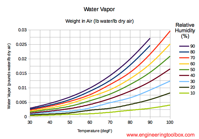
The percentage of water in the air. (%RH)
As the temperature
goes up, the air becomes thinner (density goes down).
As the temperature goes up, the amount of water in the air for a given humidity level goes up.
Air density is the 'thing' that causes drag, which is the 'thing' that causes us to have to adjust our sights for varying distances
Air density plays a major role in trajectory (change in bullet velocity over distance).
Thinner air has less resistance to bullet travel eg. drag (increased altitude or lower pressure).
Higher Relative Humidity generally indicates lower air density, and lower drag.
Air density plays a minor role in wind drift and is generally discounted for drift calculations.
Air Density can be computed from the values recorded for Pressure (station), Temperature and Humidity by the formula:
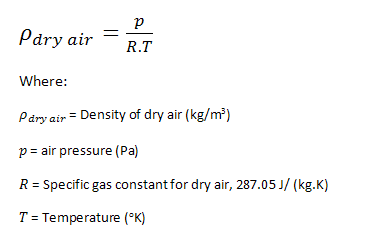
To
use the formula above, you need to convert your temperature from
Fahrenheit to Kelvin
The formula to make this conversion is:
K = (y °F + 459.67) x 5/9
To convert 75 F to Kelvin this
would look like:
K = (75 °F + 459.67) x 5/9
K = 534.67 x
0.555
K = 297.038
For your DOPE it is sufficient to record pressure, temperature
and
humidity.
Including altitude will permit referencing the results
to standard atmosphere at sea level should you ever desire to do
so
at a later date using the formulas above.
Various kinds of overcast can affect how you see your sights. This is more prominent with iron sights, but still is valuable with all types of sights.
Each of these conditions affects how you see objects and perceive dimensions, distances, size, shape and movement.
Bright – No clouds at all.
Hazy – Haze or smoke (stuff between you and your
target)
Overcast – Some clouds. Estimated % cloud
cover.
Changing – Clouds periodically blocking sun, casting
racing shadows.
Dawn or Dusk – Sun near horizon, very low angle
light, often light hitting bottom of clouds, very long shadows.
Dark
– Sun is totally obscured by heavy clouds, or has gone below
horizon.
Light, particularly coming from low angles, or from directly overhead, distorts shadows that your brain has been trained to use in recognizing the scene your eyes are viewing.
Light coming directly toward you can blind you to what lies in the smallest of shadows.
Particularly with iron sights, but still applicable to telescopic sights the view of your aiming point varies under extreme lighting conditions, and point of impact may change in a predictable way as the result. Logging the direction of illumination will help you re-create a scene for training, and will help you avoid previous errors.
The ability to 'read' the wind, and to 'estimate the wind' are vital to successful long range shooting because for a typical long range cartridge, after the bullet has traveled about 500 yards, the displacement of the bullet by the wind is far greater than the combined error of the shooter and the ammunition. A successful long range shooter must be able to integrate the wind over the course all the way to the target and provide a 'wind call' consisting of the wind speed and direction (always reported as the direction from which the wind blows) to an accuracy of about one mile per hour.
Anemometers are tools that are calibrated to display the speed of the wind, and optionally act as a weather vane to indicate the direction of the wind.
To achieve accurate readings, the typical shooters anemometer must be aligned so that the full force of the wind acts upon the detector. Aligning the detector so that it is parallel to the path of the bullet will not produce the correct wind speed because the detector (usually a propeller) does not react proportionally to the prevailing wind, but rather tends to record the maximum wind from a wide angle of presentation.
The anemometer only informs of the local wind. Observation of the wind downrange will determine if this reading can be used reliably, and will provide indications of variations in wind patterns the bullet will encounter on the way to the target.
First, it is important to know that the wind that affects the bullet initially (wind at the firing point) is often going to have the largest impact on the location of the bullet downrange. This is because once the bullet has been deflected, there is no force, except another wind, that can move the bullet back toward it's unaltered course.
Second, it is important to note that winds downrange can and will affect the path of the bullet, sometimes adding to the deflection, other times subtracting from the deflection the bullet experiences at the firing point. These wind effects can be added together as a 'vector summation' to arrive at a total deflection. When doing so, however it is necessary to include the increased time the bullet spends in each say 100 yards of range, due to velocity reduction induced by drag. More time in a given wind will result in larger deflection.
In locations with totally open flat surface between shooter and target the wind is likely to be fairly similar across the entire distance. If grass is long enough to react to the wind, you may see 'bands' of wind 'rippling' across the grass. This effect is due to the way the wind is blowing in rolling circular bands and can help you figure out the percentage of the effect across the course.
Learn to 'read the wind' by observing wind in everyday activities. If you have the opportunity to spend time in rugged terrain you will notice that wind often follows the slop. In the morning, in still air, you will be able to see that the sun heats the air toward the top before it heats the air at the bottom. Hot air rises, pulling the cooler air up the hill. In the afternoon, the shadows in the deep valleys cool sooner than the air at the top reversing the flow. This continues regardless of the weather, but local wind is often much stronger than convection flow. When wind encounters an upslope it compresses (and heats up) toward the bottom, then flows up the slope. When it encounters a ridge, or a ridge top, convection occurs which causes a swirling rolling wind. This effect occurs even for surface changes as subtle as dry grass versus irrigated crops.
This French word comes from the Latin mirare or 'to look at.' In
a
shooting context it has come to mean an optical illusion caused by
atmospheric conditions.
Mirage begins when air moves (due to
wind) or when the ground surface heats from solar radiation and
warms
the air that is in close proximity to the surface. Warm air rises
because it is less dense than colder air. Air temperature effects
how
light is bent passing through the region. As the air heats and
rises
it creates a shimmering wavy appearance by deflecting the light
that
passes through the region.
Initially this effect moves straight up in calm air and appears as vertical wavy lines, quite pronounced when viewed through magnification. As the effect continues, and the day progresses, wind will occur as cooler, denser upper air is drawn to replace the lighter warmer air near the surface. This wind will cause the vertical wavy lines to tilt.
The bottom of the wavy line will stay put where the heat caused the air to expand, and the top of the wavy line will move in the direction of the wind. When viewed through magnification (spotting scope or telescopic sights) the direction is nearly impossible to determine because of the two dimensional nature of the image.
The strength of the wind can be measured quite accurately for low speed wind, by the angle of the mirage.
15° tilt is caused by 1-3 mph wind
30º tilt is caused by 4-7
mph wind
90º tilt is caused by 8-10 mph wind
But keep in mind that what you observe may not be a wind at 90º to your line of sight. The 15° tilt you see, may be a 30º tilt viewed from 45º. Observing the motion of wind downrange for several minutes and across the width your 'front' will provide you with clues as to the direction of the wind.
Mirage can be measured at increments downrange by focusing the spotting scope (or tactical rifle scope) at ¼, ½, ¾ of the distance to the target and then observing the mirage effect.
For the 36” streamers used in High Power competition:
15º = 3-3/4 mph
30º = 7-1/2 mph
45º = 11-1/4 mph
60º
= 15 mph
75º = 18-3/4 mph
Flags or streamers can be used to measure the wind by noting the
interior angle between the flag's long (bottom) edge and vertical.
Generally, dividing that angle by 4 will yield the wind speed in
MPH.
Golfers have developed interesting wind flags. See Wind Gear Direct.
For streamers made from surveyors tape that are 3 feet long these values apply:
NOTE: This section is under research 20170218
Surveyors tape hasty flag
How does length affect wind sensitivity and streaming angle?
Correlate wind speed to flag angle with photos.
Describe test flag.
NOTE: I started trying to correlate Kestrel readings with photographs, but found I need a larger open area and more consistent wind to get usable results.
NOTE: I noticed that the longer the streamer is, the more it flutters up and down, as the wind lifts the streamer at the 'head' the weight of the 'tail' tries to collapse the response. I want to run a direct comparison of several lengths of survey tape streamers simultaneously to get some photo data of this effect.
The local vegetation will eventually react to the wind.
It is best to do your own research on the relationship between wind speed and your local flora, as there is a very wide range of behavior.
5-8 mph Tree leaves in motion
12-15 mph Small trees sway
15-20
mph Larger trees sway.
Your face is particularly sensitive to
wind, and with just a little effort you can tell quite accurately
the
direction from which the wind is blowing by the feeling on your
face,
neck and ears.
Temperature and humidity have a lot to do with how
sensitive your face and neck are to wind direction and speed.
It
is best to do your own research and record your observations in
your
own DOPE book.
0-3 mph Barely felt on the face
3-5 mph Lightly felt on the
face
8-12 mph Raises dust and loose paper from the ground.
When you begin to shoot beyond 500 yards the motion of the Earth has a measurable affect on the behavior of your bullet. By the time you are shooting 1,000 yards, the effect can be measured in inches on the target.
Its not exactly true, but an easy way to visualize the Coreolis effect on bullets is to imagine firing a bullet due East at a distant target, then turn around and fire a bullet a an equally distant target due West. The true explanation is much harder to remember and apply, and the difference is minor.
The Earth surface turns toward the East (to get the sun to come up on that side).
The bullet takes time (a lot of it) to travel from the rifle to the distant target. The time is the same for both targets.
During the time the bullet is in flight to the East the Earth has turned enough to lower the target several inches, and the target to the West has been raised the same amount. Raised and lowered because the earth is spherical, and as the dirt under your feet moves to the East it also moves as part of the surface of that sphere, while the bullet travels in what we can consider to be a straight line because its trajectory in both directions is identical.
Firing to the North and South: Targets move to the East by several inches between bullet launch and impact, so a shot to the North will hit to the left and shot to the South will hit to the right.
Firing at any angle will cause a combination of the effects (up/down & left/right).
The effect is most pronounced at the equator where the surface of the Earth is moving fastest.
Modern ballistics calculators want to know your firing location
in
LAT/LON format plus your direction of fire in degrees TRUE NORTH
to
enable calculating the effect and producing a correction to the
firing solution.
NOTE: What's wrong with this explanation is
that the bullet motion contained the Earth's rotation at the
moment
it left the barrel, and its frame of reference is that of a
spinning
globe. It does not leave that frame of reference just because it's
in
the air during flight. However as with centripetal force, when the
constraint has been removed, eg the bullet exits the barrel, it
would
(if no drag were encountered) travel in a straight line, the sum
of
all the forces applied at that moment, and not a curved line that
would contain the rotation vector. For the full story read the
WikiPedia article 'Eotvos
Effect'.
Firearm - record the following information for future reference:
Make
Model
Serial No (Acquired date & dealer, Sold date & purchaser)
Caliber
Barrel Length & Twist Rate
Chamber & Throat Measurement Date & Reading (technique & bullet used) with room for multiple readings as the throat erodes
Round Count - series of pages detailing date, ammo, number of rounds fired that day and running totals.
Ammunition
Make
Model
Load Name
Hand load; format: "charge weight" "powder ID", "bullet weight" "bullet ID", "case", "primer", "CBTO", "muzzle velocity".
Example: 41.0 H4350, 143 ELDx, HDY, CCI 200, 2.186", 2652 fps
Factory; use mfgr's long name.
Lot No.
Velocity
BC
Range Name - The name or location of the firing range.
Date & Time
Location
Time
Location
Range
Size
Speed
Direction
Wind
Light
Come Up
Lead
Shot call
Impact
Auxiliary Equipment - for example which chronograph, spotting scope, etc.
These are forms I created in Open Office (and AutoCAD) for use with my Storm Tactical DOPE book.
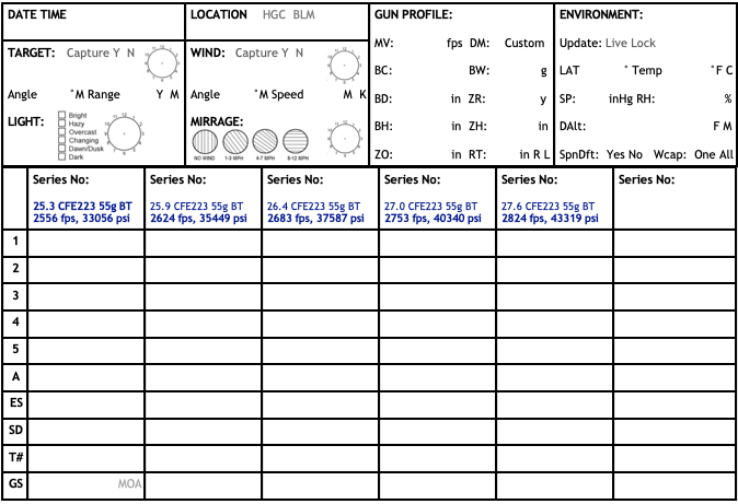
This form is pre-printed for each test load. I record velocity as
I shoot.
It gives the barrel time to cool off, and the movement
keeps me from cramping up!
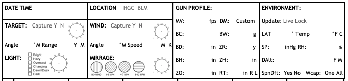
The form contains a 'block' at the top that I repeat on most of
my
DOPE forms to record environment.
The GUN PROFILE and ENVIRONMENT
blocks record Kestrel 5700 data in the order it is presented in
sub-menus.
The TARGET and WIND blocks record if I use the capture
function of the Kestrel, and my own observations.
The SERIES (vertical blocks) contain the LabRadar Series Number,
and I pre-print the load data at the top of the column.
I shoot 5
or 10 shot groups, recording velocity for each shot, the series
average MV, ES and SD.
T# is the target number (I use a large
cardboard backer, and put large numbers on it for the targets,
then
add targets to the cardboard, and finally mount the cardboard onto
the OSB backers at the range. This way I have a repeatable
numbering
system, my cardboard lasts a really long time, and its easy to
setup
& retrieve. It also makes it easy to take photos after I get
home
to document load performance.
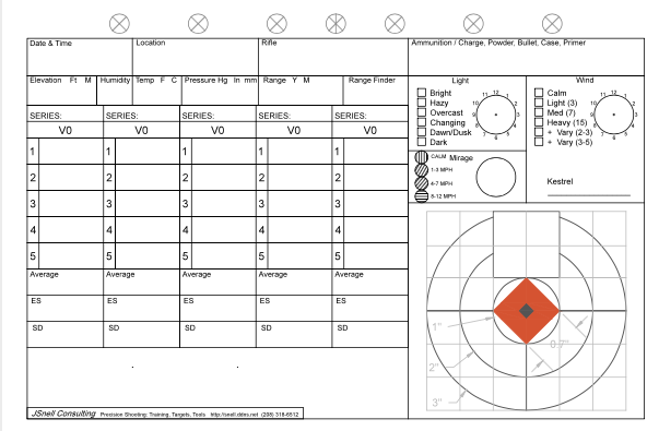
This
form is one I previously used for velocity, I still use it for
scope
'box test' and when I want to correlate a shot to a condition.
The
target is an accurately scaled down image of the target I use for
these types of tests.
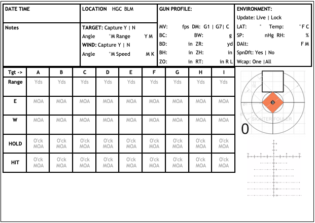
This form is one I use to record shots on targets at various
ranges one at a time.
It can however be used for multiple shot
engagements of each target.
I find myself using the blank space
that I originally intended for notes as extensions of the columns.
That seems to be true of all the forms I've created so far …
For the sake of completeness, and thus understanding, here is the
sequence of events that result in a bullet going from a loaded
round
into ballistic flight (exiting the muzzle) in excruciatingly
minute
detail.
The example load is 308 WINCHESTER / 42.8 VARGET / 175 SMK
/ HDY MATCH CASE / CCI LARGE RIFLE PRIMER / 0.044" JUMP.
This load is safe in my rifle. Please refer to my general disclaimer before duplicating this load.
QuickLoad was used to calculate the interior ballistics data below. QuickLoad has been calibrated to case length, case volume and COAL. Burning rate (Ba) has been adjusted to agree with measured muzzle velocity. Velocity was measured with a MagnetoSpeed chronograph. This load has at 98.8% fill ratio.
Processes, operations, and characteristics in this region are referred to as interior ballistics, and are completely under the control of the loader/shooter, and the rifle.
NOTE: In the following description I will only be describing the action of firing a bottleneck cartridge. Straight walled cartridges behave differently to some extent and generally are not used for high accuracy applications.
In a controlled feed style bolt action the rim of the case is already under the extractor, and there is no ejector pressure on the base of the case.
In a push feed style bolt action the
rim of the case is being pushed by the extractor and ejector
plunger
until the case stops forward movement.
This could be caused by
one or more of the following:
Bullet reaches the rifling.
Case neck reaches the end of the
chamber.
Case shoulder (at datum) contacts the chamber (at datum)
Case body, or bullet encounter obstruction.
When the case stops moving forward the extractor is forced over the rim of the case while the ejector plunger is loaded against the base of the case, thus forcing the case to 'reference' off the inside edge of the extractor and the back of the groove in the case rim. This tends to leave a gap between the bolt face and the case head. In addition, the cartridge is being forced to the right (for right hand ejection) side of the chamber.
NOTE: Bullet to case concentricity may have been excellent before the cartridge was loaded into the chamber, but now due to the ejector pressure the chances are that bullet axis to bore axis is not congruent. The only solution to this problem is to always fire the same case in the same chamber, and resize only the neck to hold the bullet. Its not perfect, but it reduces the off axis vector as much as possible.
These conditions continue as the bolt is cammed shut.
If the case is stopped, before the bolt is fully shut, by the case shoulder contacting the chamber shoulder, the case may straighten up and be forced into full contact with the bolt face. It may happen that the case is not touching the chamber walls except at the datum point, and alignment of the case and thus the bullet is determined by the squareness of the bolt face and case head.
If the case is stopped by the bullet reaching the rifling, the camming action of the bolt may be sufficient to force the bullet to begin engraving the rifling. In this case, it is possible to have the bullet stick in the barrel if the case is removed before firing. In which event, the spilled gun powder may put the rifle out of action until cleaned.
The bullet may force the case to square up on the bolt face, and not touch at datum (depending on case sizing choices). In this event, the alignment of the bullet to the center of the barrel is typically quite close, and the squareness of the bolt face helps increase concentricity and thus accuracy.
If the case is stopped by jamming the neck of the case into the chamber at or beyond the point where the chamber is relieved to accept the neck, the force fo closing the bolt may swage the case neck into the bullet, or simply not allow the case neck to expand away from the bullet during firing. In either case, extreme pressure will be experienced, and it is likely to damage or destroy the firearm. Keeping case necks trimmed to a length shorter than chamber minimum is critical to safety.
In the event a push feed action is chambering a fully sized round with the bullet seated to a depth so as to not touch the rifling, then the case is being pressed hard to the right side of the action, and whatever clearance was available is all located on the left side (due to the ejector pressing on the case head). The base of the case is not touching the entire bolt face and thus not contributing to concentricity. The case neck is off center in the chamber just as the body is. In this condition it is impossible to achieve concentricity, and this is the reason why accuracy improves with neck only sizing.
The breach is locked by camming the bolt locking lug surfaces fully closed.
NOTE: This is true for bolt action and semi-automatic actions. Both have interrupted thread style cams, its just that semi-autos only have the stored energy of their spring to load and lock a round, where the manual bolt action has a tremendous amount of leverage (bolt handle) to force the bolt closed.
The firing mechanism is now fully locked and cocked. If a safety has been engaged, it must be disengaged before the next step.
This releases the firing mechanism to drive the firing pin into the primer, this takes an average of about 3 thousandths of a second (3 mS) in most modern rifle actions.
The shorter the lock time, the more accurate an action is said to be, because the rifle has less time to wander off target between trigger pull and the bullet exiting the barrel.
Heavy springs and lightweight (Titanium) firing pins are used to decrease lock time.
The firing pin impact on the primer will drive the loaded round forward until it is stopped by one or more of the following:
Inertia. Heavy bullets can cause the round to have enough inertia at rest to allow the firing pin to detonate the primer.
This is not a desirable condition.
Extractor. The case head is engaged with a mechanism designed to pull the case from the chamber after firing. If the extractor is holding the case close to the bolt face the firing pin may detonate the primer before the case can move further forward. This is not a desirable condition.
Shoulder contact with the chamber. Absent any other retardation, the case will move forward in the chamber to the point where the cone that makes up the inside of the chamber between the body and the neck will stop the case on the cone that makes up the transition from body to neck. There is a reference dimension located at half the diameter of the shoulder called the datum line, or simply datum. The measurement is from case head to datum. This is where 'shoulder bump' is measured by reloaders. Case stopping on the datum line is the desired condition. Note that at this point there is a gap between the bolt face and the case head. Typically 0.002” is the desired gap.
Bullet engages the forcing cone. If the bullet is seated far enough forward, it may engage the rifling before the datum condition occurs. This is known as jamming the bullet into the rifling. For some rifle-bullet combinations this produces the best accuracy, by creating the best concentricity, however it is possible to get the bullet deeply engaged to the point that when an unfired round is ejected, the bullet is lodged in the rifling and the powder spills from the case. This condition can put a rifle out of service until cleaned, and is generally an undesirable condition.
See “High Speed Measurement of Firearm Primer Blast Waves”
See “Flame Spreading Process In a Small Caliber Gun”
See “Primer Output and Initial Projectile Motion”
See “Experimental Studies of the No. 41 Primer and Ignition of 5.56-mm Ammunition”
See “”
Bullet speed is 0 fps.
The primer is forced out of its pocket by the detonation. Rearward, until stopped by the breach face.
Note: If the case is forced forward far enough that a
gap as great as the primer depth occurs, a primer may be
pushed out
of the case, and gas released into the chamber similar to a
burst
case may occur. This is a symptom of severe excess headspace.
Blast wave from primer detonation
fractures gun powder near the flash hole.
Blast wave from primer
detonation forces the gun powder column to base of the bullet. The
strength of this impact is most when the gun powder fills the case
volume, and least when the gun powder is 'loose'.
Blast wave from primer detonation forces bullet out of case neck and either into contact or into engraving by rifling.
See “Primer Output and Initial Projectile Motion”
Hot gas and incandescent particles (Aluminum typically) from the primer detonation reaches the gun powder charge inside the cartridge by way of the flash hole.
The hot gas raises the temperature of the powder charge to its ignition temperature near the flash hole, and inside the gun powder charge from the center as the gas expands into the charge column.
The powder charge begins to oxidize (burn), releasing more Oxygen and other gases in the process.
As pressure inside the cartridge increases the rate of conversion of the smokeless gun powder increases exponentially.
Sticktion occurs. This phenomenon is what allows rail road engines to utilize steel wheels on steel tracks for traction. Click here for Wikipedia entry on stiction.
NOTE: According to Aberdeen Research Lab testing, the unburnt propellant charge transmits the shock of the primer detonation to the base of the bullet. In a load with little empty space the propellant charge acts as an incompressible medium and the bullet may move out of the case neck until forward motion is stopped by the bullet engaging the rifling. In a load with a large amount of free space the force of the detonation may be transmitted to the bullet as though through a compressible medium, changing the applied force and timing of the bullet engaging the rifling. In either case it is likely the bullet has been moved out of the case neck and into contact or even partial engraving before gas pressure is significant. This may be the source of the idea that accurate powder charges tend to be 90% or more fill ratio.
NOTE: Aberdeen Research Lab concluded that the engraving forces (rifled barrel vs smoothbore) are essentially nil in affecting the rate of bullet movement, and gas pressure generation. The notion of loading to jam length causing a pressure spike is incorrect.
NOTE: For Aberdeen
Proving Ground Research follow these links:
Flame-Spreading
Process in a Small-Caliber Gun - Local Copy click
HERE
Primer
Output and Initial Projectile Motion - Local Copy click
HERE
High
Speed Measurement of Firearm Primer Blast Waves - Local Copy
click
HERE
In-Chamber
Primer Force and Case Pressure Measurements of the 5.56-mm
Cartridge
- Local Copy click
HERE
US
Army RDECOM Research Laboratory Technical Report Search Page
-
Defunct Link
NOTE: This may happen too: When the pressure is sufficient
to overcome bullet inertia, the case mouth has already been
inflated
and is pressed out to the limits of the chamber. At this point
there
is no support for the back of the bullet, and the bullet is
typically
moving at less than 20fps. Until the ogive is fully engraved
into the
rifling gas will escape around the bullet at 30-40K fps. A
very
violent and potentially turbulent environment in the chamber
throat.
According to Aberdeen Proving Ground as pressure rises during
bullet
engraving, surprisingly, there is no significant difference in
pressure curves between a rifled barrel, and a smooth bore
barrel.
From
the above, you can conclude that adjusting seating depth may
have
more to do with controlling the initial shape of the
pressure curve
than anything else.
Long bearing surfaces, absolute bullet
concentricity, and minimum slop in the case to chamber are
critical.
And that is assuming you use a match grade bullet having its
center
of gravity congruent with its center of rotation.
NOTE: This may also be happening: My best guess has to do with the subtle variations in pressure vs time during the time between shot start and (for example), when the rifling is engraved. During this period the available volume is increasing as is the pressure. By increasing the charge weight, the initial volume decreases as does the available volume at the point of engraving. Powder burning characteristics (Ba or Burning Rate in particular) change as a function of pressure, thus at some point in the charge weight variation tested, the burning rate changes inversely to the charge weight enough to produce similar pressures for a several tenths grain charge change.
The bullet begins to move
The major diameter of the bullet enters the leade, a smooth straight section of the barrel just toward the muzzle from the case neck and before the rifling that is a few ten-thousandths of an inch larger than the bullets major diameter. The leade guides the bullet toward the forcing cone; a chamfer between the leade and the origin of the rifling. The leade supports and guides the bullet into engagement with the rifling. Accuracy is significantly affected by how concentric the bullet is to the forcing cone at this moment in time because the center of rotation of the bullet must be as close to the center of mass of the bullet as possible. Variations in case neck thickness, bullet jacket thickness, and accuracy of machining of this area are critical to launching a bullet that is spiraling without wobble.
The major diameter of the bullet enters the forcing cone. At this point the rifling begins to 'engrave' or 'upset' the bullet. The bullet must begin to rotate due to the spiral of the rifling. The gas that has been escaping around the bullet is now sealed into the chamber by the bullet to barrel deformation. The relationship between the centerline of the bullet, center of rotation of the bullet, and the centerline of the barrel have now been set. Ideally these center-lines should be identical.
Depending on how the bullet was seated in the case to begin with, it may have to travel some distance, probably less than 0.080" or as little as 0.000" for 'accuracy' handloads to be loaded single shot, and perhaps well over 0.100" for rounds loaded to feed in magazines in long lead rifles similar to the Weatherby design.
With the 308 WINCHESTER / 42.8 VARGET / 175 SMK example used elsewhere here, and according to QuickLoad calculations, when the bullet has traveled 0.040" to engage the rifling, or the bullet's 'jump' is 0.040"; 0.050 Seconds have elapsed, the pressure behind the bullet is about 35 psi, and the bullet is moving toward the muzzle at about 10 fps. The thing to remember is that the bullet enters the rifling quite slowly and gently.
NOTE: This graph was published by Aberdeen Research Lab in 2016 showing the position vs time for M855 (55 grain 5.56 NATO) and M856 (55 grain 5.56 NATO Tracer) bullets during the first 450 nano seconds after firing. Note that the bullet passes through contact with the rifling and engraving with no discernible variation in the rate of position change or measured force.
NOTE: A mili second: 0.001 Sec is 1/1,000 (1 thousandth) of
a second.
A micro second: 0.000001 Sec is 1/1,000,000 (1
millionth) of a second.
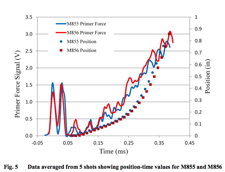
NOTE: This graph was published by Aberdeen Research Lab in 2016 showing the acceleration and velocity of a 5.56 NATO M855 bullet during the first 400 nano seconds after firing. Primer induced velocity reaches to about 0.17 mS where acceleration from propellant burning begins to takes over.
NOTE: At 0.0004 seconds the M855 projectile has traveled 0.75" down the bore, it is traveling (in that instant) 156.25 fps.
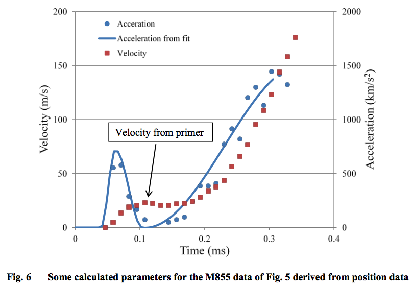
NOTE: Read the complete report by Aberdeen Research Lab: Primer Output and Initial Projectile Motion. (ARL has removed this information from their public web site – click HERE for a locally cached copy)
NOTE: The transition zone between primer induced velocity and powder induced velocity is likely the area affected by varying the seating depth of the bullet.
In our search for the ideal load we are looking for consistent muzzle velocity and consistent group size. Once a case, primer, bullet, powder charge has been decided upon the only parameter available to change is the bullet seating depth. Varying the seating depth changes the available initial volume, which no doubt changes the point on this chart where bullet velocity and the resulting increase in available volume, are governed by gas generation.
The case is pushed into contact with the bolt face.
If the primer was partially blown out of the primer pocket, it is reseated by the bolt face as the case head moves to the rear. This motion may be as small as 0.002" (neck sized case due to 'spring back') or as large as the maximum variation in SAAMI headspace, which in the 308 Winchester is 0.010"
NOTE: When you set your resizing die you are controlling the relationship between the case and the chamber. You must be careful to ensure that the CBTD (Case Base To Datum) dimension is within the SAAMI Headspace dimensions.
Pressure increases as the bullet moves forward. The volume available to the expanding gas increases. Gas generation increases very rapidly.
At some point in time, the pressure inside the case becomes sufficient to expand the case body toward the confining chamber walls. As pressure increases stiction occurs. (stiction is 'static friction').
Under some conditions stiction will occur before the case head is in contact with the bolt face. When this happens the case stretches and over time may separate forward of the web area.
Ideally the case will first contact the bolt face, then expand no more than 0.002" in length to bring the case shoulder into contact with chamber. Brand new and full length resized cases will typically expand more. Resizing only the case neck between reloading (for the same chamber) will limit the stretching of cases.
Various styles of extractors may hold the base of the case closer in contact with the bolt face during primer strike, leaving room at the shoulder for case expansion.
NOTE: One major goal of accurate ammunition manufacturing is to ensure the bullet is concentric to the center of the bore at the moment of firing.
As the case shoulder is bumped further toward the case head, the cartridge looses a bearing surface upon which to elevate the bullet into line with the bore.
Extractors generally are on the side of the bolt, and do not exert much upward influence on the cartridge case, so as support at the front is removed, the case tends to lay in the bottom of the chamber. Do not assume the case neck can support the case as the chamber is several thousandths larger in diameter in that area to allow bullet release.
Seating the bullet to a zero jump length or longer will force the case into better alignment, but may also cause the bullet to stick in the bore if the case is extracted prior to firing.
The ideal situation is to have the cartridge case shoulder in tight or not more than 0.002" loose contact with the chamber while the case head is flush on the bolt face prior to firing.
The bullet travels 1.3" toward the muzzle, volume for gas expansion increases, the volume of gas produced increases and peak pressure of 58,166 psi observed.
The bullet has accelerated to 891 fps. 0.361 seconds have elapsed.
The bullet travels 6.1" toward the muzzle, gas pressure has decreased to 29,100 psi, approximately 1/2 of maximum.
The bullet has accelerated to 1,907 fps. 0.633 seconds have elapsed.
The bullet travels 26" and is at the muzzle. The pressure is 6,450 psi, velocity is 2695 fps, and 99.92% of the powder has been burned.
NOTE: The air in the barrel at the instant of firing is compressed by the escaping gas and the accelerating bullet and creates an initial gas jet that has some potential to disturb the point the barrel is aimed to, however the more important effect this gas jet can be used for is to penetrate and remove any muzzle cover (electricians tape) that may be applied to a hunting rifle to keep foreign debris out of the muzzle. The escaping air will easily remove the muzzle cover with no effect on the shot.
The now unconstrained gas creates a jet effect as it exits the muzzle unrestricted. The jet creates a significant portion of the recoil energy produced. Typically the rifle has barely moved along its recoil axis at the point in time where it no longer has any contact with the bullet. The gas accelerates as the pressure equalizes inside and outside the barrel and then disperses in the air beyond the muzzle. High speed video shows the gas cloud typically overtaking the bullet out to a distance of one to two feet, before it dissipates, and the bullet emerges from the gas cloud.
The very rapid expansion of the gas causes the gas to cool dramatically. The 'BANG' you hear is actually more about the gas cooling off quickly than anything else.
If the muzzle is not square to the line of the bore, then gas may be released early on one side of the muzzle, this force can cause a bullet to yaw in an effect that is not altogether dissimilar to the 'PIT' maneuver used by Highway Patrol to cause a suspect vehicle to swerve.
If there are any obstructions in the bore near the muzzle that occlude the bore (stick into the area occupied by the bullet) then bullet deformation may occur, and if the obstruction is quite close to the muzzle may cause a shift in the point of impact. Lead and copper fouling creates this type of obstruction in the portion of the barrel where bullet velocity is maximum.
If there is any deformation of the bore near the muzzle that does not occlude the bore, the chances are very good that accuracy will not be affected, unless said deformation causes gas to be released unevenly to such an extent that yaw is induced in the bullet.
From this point onward the bullet is no longer under the influence of the shooter or the rifle. Characteristics in this region are referred to as Exterior Ballistics. For a thorough treatment of the behavior of bullets in this region please refer to the collected works of Brian Litz.
To visualize barrel dynamics, first remember that steel is
elastic
(in the sense that it stretches and bends), then imagine a very
slow
motion view of your rifle barrel during the sequence of firing.
I'm
going to try to paint a picture of words that explain each of
several
motions that occur in a barrel when it is fired. Once you 'see'
what
I'm talking about move on to the next description and add that
motion
to your mental image.
Just prior to firing, the barrel is
positioned horizontally, and the muzzle is drooping a very small
amount due to gravity. Thus, initially the muzzle is pointing
below
the centerline of the barrel. This type of structure is know as a
'cantilevered beam'.
See the previous section on Internal
Physics for the details, at this point in the discussion lets
simplify to the following:
The firing pin hits the primer, the
primer detonates, the primer flame lights the smokeless powder
which
burns ever more rapidly as the gas it generates is confined by the
cartridge, bullet, chamber, bolt, and barrel. Pressure inside the
cartridge increases very rapidly to drive the bullet out of the
cartridge case. The forward motion of the bullet creates an equal
and
opposite recoil force. Lets call this the axial motion.
Recoil
starts the barrel moving backward, the recoil force is translated
through the recoil lug to the stock, where the shape of the stock
typically causes the muzzle to rapidly move upward.
Remember
how the muzzle was drooping below the centerline of the barrel?
Now,
as the barrel starts to move upward the muzzle lags the centerline
of
the barrel until the stiffness of the barrel forces the muzzle to
bend upward, overtaking the centerline until the muzzle reaches
some
displacement above the centerline where barrel stiffness causes
the
muzzle to start bending downward with respect to the (moving)
centerline of the barrel. This is the 1st Mode of deformation of
the
barrel. There are many others, but this on is of primary concern
to
us with regard to developing a load that shoots with minimum
dispersion.
In a particular 308 Winchester load with a 175
grain bullet, fired from a 26 inch 1:10 twist barrel, the maximum
internal pressure of 55,338 psi is achieved at about 0.360 mSec
when
the bullet is only 1.24 inches down the barrel and is moving about
846 feet per second. By the time the bullet is 12 inches down the
barrel the pressure has dropped to about 15,000 psi, and the
bullet
has accelerated to about 2294 feet per second. Just as the bullet
exits the 26” barrel it has reached 2691 feet per second, and
93,752 revolutions per minute. The pressure has dropped to about
6,727 psi, 1.329 mSec (0.001329 Seconds) have elapsed.
The
barrel is elastic so it winds up some amount while the bullet is
in
the barrel. Lets call this a torque vibration. We will never see
the
torque vibration by its self, but when added to the vertical
vibration it creates a small horizontal component we will call the
horizontal motion.
In addition to all that, the sound of the
firing pin, the explosion of the primer, and the rapid expansion
of
the smokeless powder gas causes the barrel diameter to expand.
NOTE:
This is the OBT (Optimum Barrel Time) theory's main component.
The
largest component of this motion starts in the center of the
chamber,
and travels down the barrel to the muzzle at the speed of sound in
steel, about 16,000 fps. Once the radial expansion reaches the
muzzle
it reflects nearly perfectly back toward the bolt face, but is
distorted when it encounters the barrel threads, recoil lug, and
uneven thicknesses of the action. The radial expansion is called a
'shock wave', and it bounces back and forth between the ends of
the
barrel causing the muzzle diameter to expand when the wave is
present
at the muzzle. The muzzle returns to its nominal diameter when the
wave is at the receiver end of the system. Thanks to Chris Long
http://www.the-long-family.com the author of “The Shockwave
Theory”, we have a very good idea when the 'quiet' nodes occur for
a given barrel length.
http://www.the-long-family.com/OBT%20Table.pdf
During the 1.329 milliseconds that it takes my 308 Winchester 175
grain example to exit the 26 inch barrel, the shock wave has been
to
the muzzle and back to the receiver 5 times. In this example the
shock wave is at the receiver just when the bullet exits the
barrel.
Lets call this a radial motion.
Varmint Al has graciously
permitted me to include some of his engineering simulations to
illustrate what is occurring.
Refer to "Full 3D Finite
Element Analysis of a barrel's first few modes shapes and
frequencies
calculated with the LS-DYNA code."
While the information
on this page may be a bit technical for some, the takeaway
information is that the largest and most important deformation of
the
barrel (with respect to where the muzzle is pointing at bullet
exit)
is the vertical Mode 1 Cantilever Bending motion.
Now refer to "Varmint Al's Barrel Tuner Analysis ..." The
first chart "Typical Muzzle Projection Curve" shows a graph
of the Mode1 deformation (Muzzle's Projection to 100 yard Target
in
Inches) versus time.
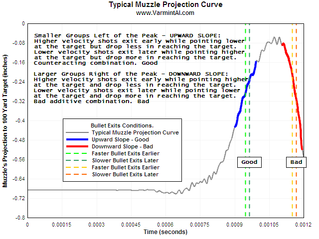
Remember
that we are starting out with the barrel drooping slightly due to
gravity, at the shot start recoil and stock shape combine to cause
the muzzle to bend downward then upward. Thus the Muzzle
Projection
To 100 Yards numbers start at about -0.68 (about 11/16" low) and
move upward to about -0.06 (about 1/16" low). This effect begins
at about 0.0006 Seconds and peaks at about 0.0011 Seconds. Bullets
exiting the barrel during the barrels upswing (0.00075 - 0.00110
seconds) will tend to impact on the target closer together than
bullets exiting the barrel after the motion reverses (0.00110 -
0.00120 seconds) because the bullets with faster muzzle velocities
exit sooner and are pointed lower than slower bullets which are
pointed higher. In other words the vertical barrel motion tends to
cancel out muzzle velocity variations in this region. The inverse
is
true after the barrel reverses motion, causing much larger
groups.
There are a couple of ways to cause the bullet to exit
before the peak of barrel deformation, but the one we are going to
focus on is changing the velocity of the bullet by changing the
powder charge. This is called a Ladder Test or more precisely an
Audette Ladder Test.
Al explores the effect of barrel motion
on vertical dispersion by simulating a ladder test (increasing
muzzle
velocity by 25 fps per shot) then zooming in on the peak range of
barrel motion and plotting shots against their 100 yard impact
points
in this chart, which pretty much says it all.
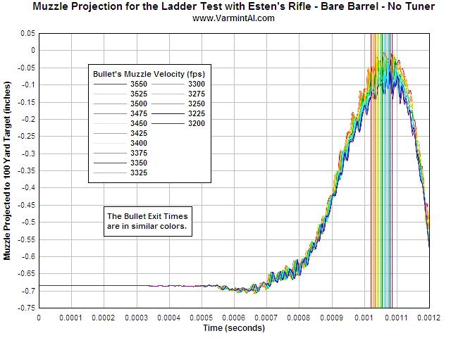
The barrel starts out sagging due to gravity.
Recoil
and barrel deformation cause the muzzle to point downward
slightly,
then upward by nearly 3/4" projected to 100 yds by 0.001 seconds
from shot start.
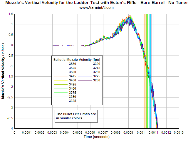
On
this chart, positive vertical velocity is downward, negative
vertical
velocity is upward (against gravity).
The barrel has no
vertical velocity before the shot.
At shot start the barrel
moves downward at a rate approaching 1.5 inches per second then
reverses to achieve between -1/2 and -2.5 inches per second upward
velocity during bullet exit window for the shots of the ladder
test.
This vertical velocity is retained by the bullet after
exit.
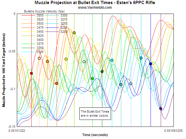
Each
shot has a different velocity by 25 fps. Each exit time is plotted
on
the Muzzle Pointing Curve (MPC). By taking the vertical axis value
for each shot a virtual ladder test is performed.
NOTE: A key
takeaway here, it to realize that the major muzzle movements
(vibration) are identical for each shot, without regard to muzzle
velocity, and that there are some very minor vibrations that are
sensitive to muzzle velocity which only account for extremely
small
variations in the muzzle pointing position at a given moment in
time
for each shot. The wave shapes in this region of the chart are
similar in frequency, and differ mostly in amplitude. Also note
that
the total variation in muzzle velocity is 350 fps in this
example.
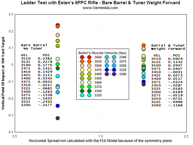
Varmint
Al says:
LADDER TEST RESULTS.... The total vertical spread
with the bare barrel is 0.5539 inches compared to 0.2097 inches
for
the case with the tuner and the weight forward. The chart
represents
where the bullets would strike at a virtual 100 yard target for
the
range of velocities listed. For Esten's Rifle with no tuner, there
are three groupings near 3475 fps, 3375 fps, and 3275 fps. These
muzzle velocities could be loads where the rifle is "in tune".
The yellow circle (3475 fps) is under the gray green circle.
We
are mostly interested in the bare barrel results because most of
us
are probably loading for hunting or tactical shooting, and won't
have
a barrel tuner.
The shot clustering Al refers to is exactly
what the Audette Ladder Test is designed to reveal, without
needing a
computer to figure it out.
The small vertical variation at 100
yards is the reason we want to do the Audette Ladder Test at
longer
ranges so as to amplify the effect. The down side of using longer
ranges for ladder tests are that wind can have a significant
effect
on the horizontal component (which we should ignore), and a minor
effect on the vertical component which may be pretty small to
begin
with. The best time to do Audette Ladder Tests is in very calm
wind
condition, with as little cross wind as possible.
You must be
able to accurately label the bullet impact and the charge that
created it. If you have target butts where an assistant can pull
the
target down, record the shot, and put it back up, then the longest
range you have is what you should use. If you don't have that
luxury,
and your spotting scope runs out of resolution before the distance
you want to use, consider a camera system, or else you'll have to
approach the target between each shot to log it. Don't assume the
ladder will be an incrementally ascending or descending string of
shots, as that just about never happens.
The Celestron C90 MAK telescope with the appropriate erector and eyepieces can resolve bullet holes to just about the maximum distance the current mirage conditions will allow - generally 30 cal to about 300 yds. This spotting scope is quite inexpensive compared to the typical shooting spotting scope, and is quite a bit more fragile.
You can color your bullets with a permanent colored marker, and some of that color will rub off on the target paper as the bullet travels through it. For cases where the bullets impact a little apart from each other, this technique (which might take a little time to perfect), is the fastest, easiest, and least expensive way to get the 'which bullet made which hole' information.
Some people have suggested that a
ladder test should be a group fired with each charge increment. If
you do this, you'll need to fire enough shots to burn your barrel
out
before you are done, and unless each shot in the group has nearly
the
same muzzle velocity you'll need to fire enough at each charge
increment to get a valid statistical sample to determine where the
center of the group is (not the group size). Each shot in the
ladder
test tells its own story quite accurately. There are a number of
actions you can take to improve your group size once you figure
out
your powder charge
With all that in mind, Varmint Al has this
to say:
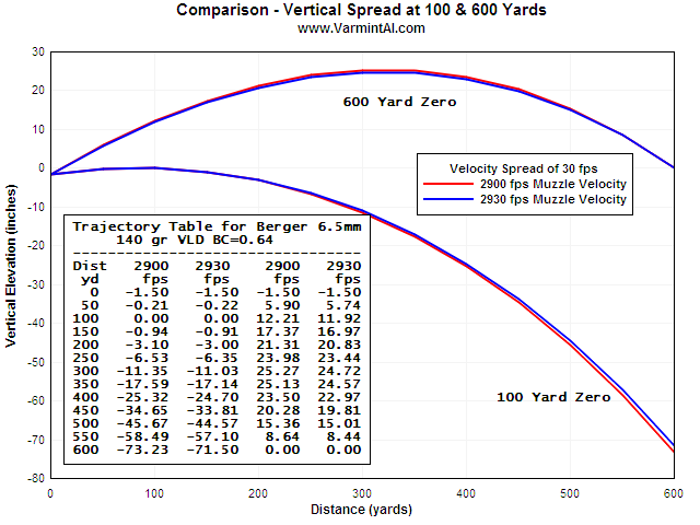
LONG
RANGE TUNE.... Here is an interesting set of trajectory plots. No
matter how carefully one loads his ammo, there are going to be
small
differences in muzzle velocity. Consider a load with an average
muzzle velocity of 2915 fps with a muzzle velocity variation of 15
fps. Then consider this load tuned for zero vertical at 100 yards
that overcomes that small difference in muzzle velocity.
This
same load will be out of tune by 73.23-71.50=1.73 inches of
vertical
at 600 yards. However if the load is tuned so that there is
12.21-11.92=0.29 inches of vertical at 100 yards (with the slower
muzzle velocity hitting higher) then there would be zero vertical
at
600 yards. This chart is for a 6.5mm 140 gr VLD bullet with a 0.64
BC. A similar chart or table can be made for each long range load.
If
you are in tune for zero vertical at 100 yards, you will not be in
tune for zero vertical at 600 or1000 yards.
I think another way of saying this is that you should do ladder
tests at long ranges. In terms of curve fitting, if you have lower
vertical dispersion at longer distances, the vertical dispersion
increase at shorter distances is smaller than if you set it up the
other way around.
One more point to consider; when setting up
your ladder test, keep in mind your ultimate target. If you are a
hunter in particular, what is the longest range you will allow
yourself to take a shot at a game animal? What is the size of the
animals vital zone? How large is one click on your scope when
projected to that range? If you can get your vertical dispersion
inside one click at your max range you really only have to worry
about accounting for wind where the bullet travels to the target.
In
summary; while the bullet is inside the barrel, the barrel moves
vertically, horizontally, axially and radially with respect to the
initial centerline of the barrel. Regardless the velocity, the
barrel
moves substantially identically between shots. Since each shot has
a
slightly different velocity, getting the bullet to exit the muzzle
when the muzzle is nearing it's peak upward position is the secret
to
achieving accuracy. Using a ladder test to map the barrels motion
versus muzzle velocity over a small range of change will paint a
picture from which it is fairly easy to select a powder charge
that
will cause your bullets to have little vertical dispersion. You
only
need, and should only use, one shot per charge weight at this
stage
of development. To use more shots at a given charge tends to
confuse
more than anything else. Ideally, you must know the following
about
each shot:
General Information: Case, Primer, Bullet, Seating Depth, Power, and any case preparation notes.
Shot Number
Charge Weight
Muzzle Velocity
Point of Aim
Point of Impact
Now that we have an appreciation of barrel movement during the shot, we need to address a couple of other topics before we move on.
Right about here, a lot of you may be wondering about Scott Satterlee's 10 shot Load Development Ladder Test. Scott noticed that there is a velocity change plateau in the typical incremental charge ladder test, and that the lowest velocity variation load occurs in the middle of this plateau.
I have not been able to find any theory, finite element analysis, or simulation that explains why this plateau occurs, but occur it does, and it can be used to quickly choose a correct powder charge for an accurate long range load.
There are a number of videos, and much internet discussion of how to perform Scott's test. Here's a link to the 6.5 Guys interview with Scott Satterlee on the subject. One observation that Scott makes and I agree with is that once a velocity has been identified for a given rifle, case, primer, bullet, the powder can be changed, and as long as the powder charge achieves the same velocity, it will be an accurate load. I believe this is a demonstration of all of the barrel movement observations detailed above. Due to the variations in burning rate and total energy of each powder, I believe there are a limited number of powers that will demonstrate suitability over the entire range of use. For example, a faster powder may, when the correct velocity is found, only fill the case to 75%, and because it has such a large open space within the case, it may not ignite the same way every time, and thus have an unusably large velocity spread. Ancient wisdom tells us that the best loads occur at above 90% fill ratio, with the slowest powder that will achieve the desired velocity.
Ammunition must fit the chamber for best accuracy.
Simply 'being in the chamber' is not fitting into the chamber. To fit, a loaded round must be very close to all of the dimensions of the chamber, so that the center line of the bullet is positioned as close as possible to, and parallel with the center line of the barrel. The bullet must travel down the barrel with its center of rotation very close to its center of mass.
When a virgin or full length resized case is chambered, there is typically a significant amount of slop in the length and diameter of the case. Case misalignment in the chamber can destroy any benefit of bullet to case concentricity.
When a new case is fired it expands under tremendous pressure to fit very tightly into the chamber machined into the barrel. As the temperature of the case returns to normal, the case (because it's brass) contracts very slightly in diameter and length. The fired case is now as close to the chamber's dimensions as it can be. Try not to mess that up! Correct neck sizing alone is sufficient to reload this piece of brass, and if it is done with a conventional die, ensure (by measuring before and after) that the neck expander does not alter the headspace, or diminish concentricity. Hand dies are the best because they don't ever pull the case from the neck, and they are small, accurate, concentric, fully support the case, and easy to use anywhere.
In order to manufacture accurate, and consistent ammunition, you need to know some characteristics of the ammunition. We measure and record the following information for reference, and to inform our adjustments.
A case fired in this chamber will expand in all directions to
fill
the chamber completely. As the case cools it will spring back
about
0.002" in both length and head diameter. Measure several fired
cases. The measurement should be very consistent. Use this
measurement as a reference when setting up your full length sizing
die, and when periodically checking for case length growth. Note
the
date the initial and subsequent measurements were taken. Compare
to
the barrel's round count log. This measurement should not change
significantly.
NOTES: Case measurements to datum lines are
made by inserting the cone shaped shoulder of the case into a hole
with an inside diameter of the reference size, and measuring from
that point to the case head. With digital calipers and an adapter
this measurement can be made so that it is simple and repeatable,
but
since the adapters have the rim of the reference hole slightly
eased
at the junction of the face of the adapter (to prevent marking the
thing being measured, and because they are not laboratory grade
tools) no two adapters will have quite the same measurement. In
addition, measuring fired cases typically means measuring them
before
the spent primer is removed. Many actions have a tendency to
extrude
primer cup material into the gap between the firing pin and bolt
face. This tiny extrusion will completely mess with your CBTD
measurement. Either find a way to decap the case without changing
anything else (difficult at best), or modify your measuring
equipment
to ignore the area around the primer, while still taking the base
of
the case as one reference point. I did this by using a precision
flat
washer on an anvil affixed to the caliper jaw. The CBTD for a
given
rifle should not change unless work is done to the bolt or
chamber.
Cases that have been reloaded and fired several times without
having
the shoulder 'bumped back' may still chamber easily, and if they
do
so adequately for the purpose of the rifle should not be adjusted.
If
the rifle MUST CHAMBER the cartridge (defensive, dangerous game,
etc.) then full length resizing is recommended. Firing high
pressure
loads (at or exceeding SAAMI PMax) will cause CBTD to grow to the
point where the fired case will not chamber. This is an indication
that the load should be reduced.
Date
Reference Bullet
Round Count
Remeasure every year, or 1,000 rounds.
This measurement is
made by placing a bullet into the chamber and gently advancing it
to
the point where it is stopped by the origin of the rifling. Using
a
modified case to hold the bullet in place while chambering it can
work, but typically won't because the bullet will change position
too
easily. You can make this measurement from the muzzle with a rod.
Start by finding the bolt face to muzzle distance, then place a
bullet into the chamber and gently advance it until it stops
against
the rifling. Now find the muzzle to bullet tip measurement with
the
rod, and calculate the bolt face to bullet tip to determine COAL
(Cartridge Over All Length). This is the number often found in
reloading manuals for bullet seating depth reference. Hornady
sells a
nice tool that uses a case to reference from datum while advancing
the bullet. The measurement is then taken from the tool's case to
bullet ogive. To get a true reading, compare the tools case to a
fired case (CBTD) and add 0.002" for spring back to calculate
BFTO.
NOTES: Use a reference bullet from each stock number of
bullet you load in this rifle. Each bullet has a unique ogive
shape,
and a unique dimension from the point of ogive contact to the
point
of the bullet and to the base of the bullet.
Date
Reference bullet
Round count
Remeasure annually or every 1,000 rounds.
This is the same
measurement as above except it is referenced to the base of the
case.
NOTES: Case Base To Ogive (CBTO) and Bolt Face To Origin of
Lands (BFTO) are not identical, nor should they be.
SAAMI defines headspace as the
distance
from the case head to the case datum, and establishes tolerances
to
coordinate with the chamber dimensions and tolerances. The actual
meaning of headspace is just that, the room into which the head of
the case can expand under pressure.
On second and subsequent
firings CBTO should be between 0.002" and 0.004" less than
BFTO.
You can determine the dimensions in your rifle by several
methods.
The easiest method to determine BFTD (Bolt Face To
Datum) is to measure a fired case and add 0.002" for spring
back.
If you use the Hornady Lock-N-Load
(formerly Stony Point) Overall Length Gauge to determine the
position
of your 'zero jump' or distance to the rifling, you must be aware
that the gauge measures from the case datum to the bullet ogive,
and
you will need to compare the Hornady supplied case to one of your
fired cases to arrive at any meaningful measurement derived from
the
case head.
To compare Hornady Lock-N-Load test case with your
fired case, measure each with the Hornady Lock-N-Load Bullet
Comparator using the correct insert for your case's datum
dimension.
If the Hornady case is shorter, then add the difference plus
0.002"
for spring back. If the Hornady case is longer, then subtract the
difference and subtract 0.002" for spring back.
To locate the correct dimensions for any SAAMI cartridge look it
up at http://saami.org under 'Info and Specs', 'Cartridge and
Chamber
Drawings', rifle, pistol etc. then use the index to find the
cartridge you are interested in.
NOTE: SAAMI Headspace is
measured from the bolt face to the datum line. For example the 6.5
Creedmoor Chamber drawing shows headspace as 1.551" MAX, 1.541
MIN, from which we can estimate that a case measuring
1.551-0.002=1.549 was fired in a MAX chamber and a case measuring
1.541-0.002=1.539 was fired in a MIN chamber.
NOTE: In my
experience, if pressure is kept below SAAMI PMAX for a bottle neck
cartridge it can be neck sized a very large number of times before
requiring trimming or full length resizing. Cases fired at or
above
PMAX will not last long at all, and their dimensions will exceed
those of once fired (with less than PMAX loads) very quickly. When
and if your cases stretch from repeated reloading cycles using
only
neck sizing to the point where they are at or longer than your
chamber, first check their CBTD and if necessary run a full length
sizing operation on the case(s), then (and always after a full
length
resizing,) trim to length.
Accurate to 0.0001" or better to check for excess pressure.
NOTES: There may be little value in measuring case heads or
primer pockets for expansion to relate to firing pressure.
This
article by Denton Bramwell leads to the conclusion that
there is
too much noise in the method to be valid, and that there are three
alternatives:
Use commercial ammunition.
Reload, and stick to the book loads.
Reload, study the book and get a strain gauge.
Requires expensive micrometer, and excellent technique to obtain credible readings.
Capture a reference reading on a first firing (virgin brass) of the same brass you reload.
For routine checks use a case gauge.
Recommended tools: RCBS Digital Micrometer 1", Hollands Third Hand Micrometer Stand, Harbor Freight Digital Micrometer .
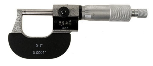
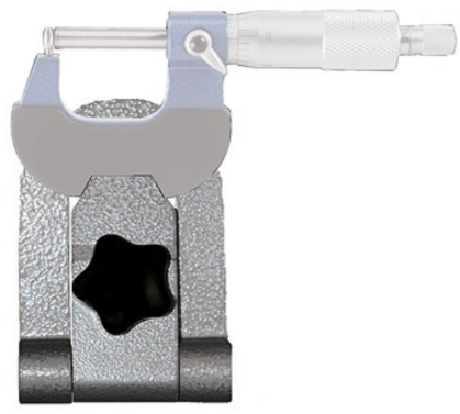
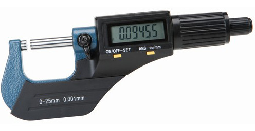
NOTES: Hodgdon
Reloading on Monitoring Pressure of Reloads .
Summary from
Hodgdon page:
Low pressure rounds (30-30 Win)
Pmax = 0.0003"-0.0004" expansion.
Modern (223 Rem) Pmax = 0.0004" - 0.0005" expansion.
Modern (308 Win) PMax = 0.0005" - 0.0006" expansion.
Magnum (300 Win Mag) PMax = 0.0006" - 0.0007" expansion measured on belt.
BOTTOM LINE: If your primer pocket expands to the point where primers fall out, your load is way over SAAMI PMax.
To know what length to return the case to if/when it needs to be trimmed.
If you are full length resizing you need to check and trim on every reloading.
If you are running a 'hot load' or a load exceeding SAAMI PMAX the case will likely stretch every firing and fail after fewer firings.
Recommended tool: LEE Case Trimmer Cutter and Lock Stud combined with the LEE Case Length Gauge and Shell Holder for the cartridge. I buy these as sets so I have one assembled for each cartridge I reload for (including pistol). It is a very small tool, easily packed for loading at the range, is dead accurate, very repeatable results, and quick. It can be powered by a cheap 1/4" screw driver motor.
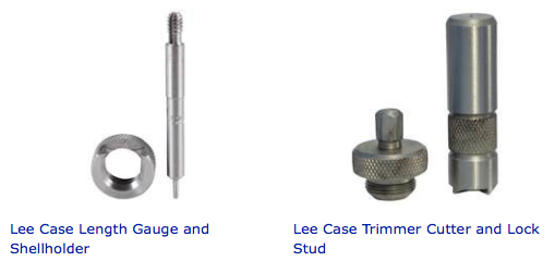
To know when the case should be trimmed.
Generally assumed to be about 0.002" smaller than the chamber neck diameter.
This measurement is difficult and requires a delicate touch because the neck wall is thin and easily distorted, and without a bullet in the neck it is very easy to push out of round with a caliper. Recommend you use your 1" micrometer, a light touch, and take samples of 10 cases to find the true average dimension.
An average for the brand (and manufacturer's run) of the case you are using.
This measurement is critical to the neck sizing process.
To achieve a target neck thickness
measure and average 10 samples at a minimum of 4 locations 90
degrees
apart on each case.
In the course of making these measurements,
you will begin to recognize where the maximum wall thickness is.
Try
to make one of your measurements at that location, and another 180
degrees away from that point. On good quality cases, your table of
measurements should feature 3 similar readings and one maximum
reading.
This measurement requires a specialized tool called a 'Tubing Micrometer' featuring a ball style anvil and a flat contact point.
When you turn your case necks your target thickness will be the average case neck thickness or just a few 0.0001's less.
Recommended tool: RCBS and Mitutoyo make the style of tubing micrometer necessary for this measurement.
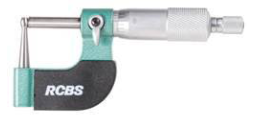
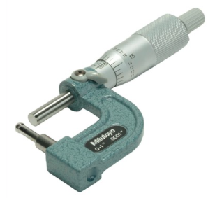
NOTE: The Mitutoyo micrometer has a straight shank under the anvil that allows you to easily install a stack of washers to quickly position the anvil the same distance inside the case neck on every measurement.
Measured from shoulder datum line to case head. Generally taken to be between 0.001 and 0.002 inches less than bolt face to chamber datum line due to brass spring back after firing. As you are resizing your brass (conventional full length resizing), keep referring to this measurement to ensure you do not change it more than -0.002" (also known as "bumping the shoulder back"). The difference between this length and the bolt face to chamber datum line is properly the rifle's headspace, or 'space for the head to expand into during firing'.
Recommended measuring tools: Digital Caliper with Hornady Lock-N-Load Overall Length Gauge and Hornady Lock-N-Load Bullet Comparator (with correct inserts)
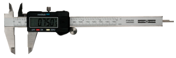
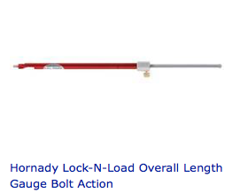
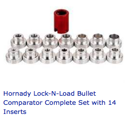
Make up a solution of 1 shot of water and just a tiny speck of
dish soap. The soap is to reduce surface tension so that you can
accurately install the water into the fired case.
Use a pipette
(long skinny dropper) to fill a fired case and check that no
bubbles
exist in the case. Stop filling when the water is exactly at the
top
of the case neck.
This test should be conducted on a fired case
that has been trimmed to your standard trim length.
Weigh 10 empty cases and keep track of case number and weight.
Fill a case to exactly full with the water solution.
Weigh the filled case. Deduct the dry weight. This is the weight of the water representing the interior volume of the case. The exterior dimensions of the case have been constrained by the firing chamber. Thus the variation in water weight between cases represents the variation in interior volume, which is caused by manufacturing processes which typically leave one side of the case thicker than the other.
Record the average of 10 or more cases for each headstamp (and or lot #) of brass you use.
If the case volume (by weight of water) goes down, there is a good chance that if the load is near Pmax in the original brass, the new brass will be over Pmax, perhaps significantly.
This situation occurs routinely when you move from using say a Hornady case to a Prime or Lapua case. Prime and Lapua have thicker walls, less interior volume, and will create higher pressue with the same load.
You should start over at the beginning, to work up a new load, when changing to cases that vary in case volume by more than 1% of the 10 case average established originally. (for 308 size cases, 223/5.56 cases are more sensitive).
This is your 'load to' dimension for seating depth, do not use COAL (Case Overall Length) because the dies that form pointed bullets allow significant dimensional runout in the nose of the bullet, from bullet to bullet within the same manufacturing run, and much more so between different bullet forming dies. You can however record COAL as long as you note the OGIVE TO NOSE length and tolerance.
Do not let this dimension get to within 0.001" of the FIRED NECK DIAMETER or you may experience a pressure event.
MAXIMUM NECK WALL THICKNESS - on most case brands there will be a narrow area of greater thickness.
MINIMUM NECK WALL THICKNESS - on most case brands the min and average neck wall thickness will be very close to identical.
TRIM TO NECK WALL THICKNESS - if you are going to get your bullet concentric with the bore you need to eliminate the neck wall high spots. Try not to remove so much much material that you change the average or minimum thickness, or your sizing die may not work correctly. Inside or Outside neck turning? I prefer outside because I can see what I'm doing, and I can make adjustments without buying a new tool. Reaming the inside can work, but it's tricky, and the dimension is fixed for each expensive reamer.
Remember the objective of neck turning is to achieve greater concentricity between the loaded round and the barrel. If the loaded round is laying in the chamber supported by the neck and base the chances are that the bullet will not enter the barrel concentric and a wobble will result. If from round to round the thickness of the neck varies, and or the thickness of necks vary around the neck, then the bullet is presented to the barrel that much differently each time, and it is not practical to attempt to present the cartridge to the chamber in the same orientation each time.
Another objective of neck reaming or turning is to create equal tension of the loaded bullet. Refer to the beginning of this article where the discussion of bullet travel at firing describes the sequence of events and lists pressures and velocities. Uniformity of neck tension will result in uniformity of bullet presentation to the forcing cone. Increasing the neck tension can retard bullet motion and generate higher chamber pressure when the bullet begins to move. This can improve consistency. Generally neck tension expressed as 0.002" of neck expansion during bullet seating is normal and sufficient. More is ok, less may lead to bullets not having enough tension to remain where seated.
The barrel first has a hole of 'BORE'
dimension drilled through its length. Next a 'rifling tool' cuts
'rifling' groves into the bore. The groove diameter is typically
used
as the caliber designation of bullet diameter. The bore diameter
however is the dimension of the point of first contact between the
bullet and the rifling. Typically the breach end of the bore is
chamfered. The exact point of first contact between the bullet and
the bore was established when you measured CBTO. The shape of many
bullets provide a curved contour from the bullet datum line (point
of
contact with the bore diameter) to the maximum diameter of the
bullet, and on to the point at the base of the bullet where its
diameter is less than the bore. Some bullets shape in this area is
a
cylinder with straight sides. The bullet receives its stabilizing
spin force by being engraved by the 'lands' (remaining surface of
the
original bore diameter). The strength of the bullet material being
so
engraved to a large degree determines the maximum twist rate for
the
bullet. The length of the bullet subject to engraving affects the
ability of the bullet to align concentric to the bore, and affects
the net resistance to movement (friction) each bullet
presents.
Bullet to bullet variations in bearing length affect
muzzle velocity by changing the rate of change in the combustion
chamber size as the bullet move into the barrel and thereafter
until
the bullet exits.
To measure bullet bearing surface, equip
your Hornady Bullet Comparator with two Ogive inserts of the
correct
datum (bore) size. Measure the distance from the bullet tip ojive
to
the bullet base ojive (on the boat tail typically). Sort bullets
by
this dimension.
The cases you use for testing should have been fire-formed to the chamber, trimmed to length and deburred at a minimum, and only neck sized. This will give you reasonable uniformity in presenting the bullet to the rifling and providing uniform case volume.
There are many procedures you can apply to your brass to increase uniformity, however they only add a very small increase over the fire-form, neck size protocol. Arguably the next most important case preparation you can do is to make the neck wall thickness uniform, thereby centering the bullet on the barrel axis more uniformly. Neck tension uniformity is important, and making the neck wall thickness uniform tends to make neck tension uniform. Interestingly bullet speed in the first few thousandths of an inch of its initial travel are quite slow. In my 308 Winchester example, the 175 SMK is moving at 62 fps by the time it has moved the first 0.010", about the same speed as though the bullet had fallen 1.4 feet. Obviously the force required to upset the bullet into the rifling is going to come from pressure not velocity! Also obviously, the bullet has plenty of time to 'rattle around' if it isn't presented perfectly. Making your ammunition co-linear with minimum runout is probably the second most important thing. The first of course is to select a powder and charge that can tolerate variations larger than your error in producing it.
Brass cases will eventually work harden wherever the dimensions are changed during the firing-reloading cycle. In particular the case neck is likely to become so brittle that it cracks. Annealing the case neck is fairly easy to do with nothing more than a propane torch, a deep well socket, a drill to spin the socket, and a semi-dark room to allow you to observe the case color change with the application of heat. Oh yeah, you'll need somewhere to put your hot cases until they cool, and somewhere to put your hot tools to allow them to cool. Use a deep socket that protects the case from the base to the shoulder-body junction or just slightly above. Install the socket on the drill and set the drill to the slowest speed. A battery screwdriver works very well for this. Insert the case with the neck exposed. Light a propane torch. Turn the lights down in the room until it is easy to see the case neck start to glow red. Start the drill, and use the torch to heat the case neck from the shoulder junction to the end where you trim it. As soon as the case starts to glow at all (it will be a very dull red), its time to remove the case from the flame. Dump the case out of the socket and put a new one in. Repeat.
Annealing your cases will make the brass soft and pliable. Do not allow the heat to travel below the body-shoulder junction to prevent softening parts of the case that should not be soft. If you first prepare the case necks by trimming or reaming, and trimming to length, and neck sizing, then annealing you will get very uniform neck tension and bullet release. Your cases should last nearly indefinitely. You can anneal between every reloading or as infrequently as once every 10-20 loading's maybe. I've come to the conclusion that annealing between every reloading doesn't hurt anything, and makes it easy to keep track of what you should be doing.
See Case Annealing in this document
There are two major methods of improving primer pockets, and two reasons for doing so.
Military surplus brass has had the primers crimped into place. When these cases are deprimed there remains a ring that interferes with primer insertion, and the diameter of the primer pocket may be a little too small at the top. To correct this, a primer pocket swager is used to force the correct dimensions by brute force. A tiny amount of Imperial Die Wax (which should be a staple on your reloading bench) helps keep the force down, and the surface finish up.
Preferred tool: RCBS Primer Pocket Swager Combo This tool can also double as a stuck case remover with the addition of a 1/4-20 bolt and 1/4-20 tap. This is one of those operations that require a strong press. If you use this on a weak press, you run the chance of damaging the press alignment. There are several standalone primer swager tools.

The second reason is to achieve uniform primer ignition by placing the primer firmly at the very bottom of an accurately formed primer pocket. This is achieved by reaming the primer pocket using a cutting tool to remove the brass at the bottom until a uniform depth flat surface exists.
Preferred tool: K&M Primer Pocket Correction Tool Comes in large rifle and small rifle sizes.
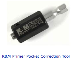
In all but the most expensive of cases, the primer flash hole is formed by a punch. This leaves the inside of the case at the top of the flash hole very ragged with waste brass. A small pilot drill is used to chamfer the top of the flash hole to clean it up. The idea is that when the primer detonates the hot gas and primer material will enter the powder chamber the same way for each case, thereby causing uniform ignition. As a theory it sounds good, the work is easy to perform and you only do it to the case once. What's to loose? (that's my way of saying I have no idea if this makes one bit of difference but my OCD says since I'm already doing everything else I might as well do this and have done with it!)
Preferred tool: K&M Professional Flash Hole Uniformer Comes in 0.080" and 0.062" for large and small rifle primers.
When a case neck is trimmed to length, there will be sharp edges inside and out that need to be chamfered.
If you are loading 'regular' bullets you could use a 'regular' chamfering tool, but if you plan to load any boat tail bullet it is better to use a chamfering tool with a shallower angle to match the shape of the base of the bullet. The shallower angle will not interfere with loading 'regular' bullets (with flat bases).
There are a lot of chamfering tools.
One day when I'm rich and famous, I'm going to get the K&M set. Until then I'm stuck with the Lyman tools. Oddly K&M doesn't make an outside tool.
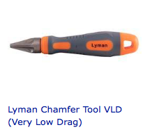
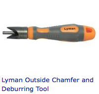
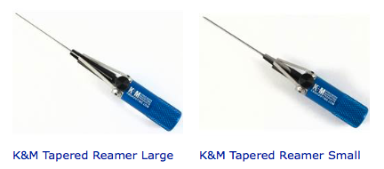
Turning your case necks reduces a major accuracy detractor - the variation in neck wall thickness that forces your bullets to be off the center line of the barrel.
Neck Turning is a commitment to both accuracy, and technique to be followed for the life of the cases so treated. Typically a case that has been neck turned will not function correctly in a conventional sizing die of either configuration (FL or Neck) because the neck wall thickness has been altered. Conventional bushing type dies may be used. I recommend using Wilson hand dies with bushings to compliment neck turning.
You will need to have the correct size bushing. You can calculate the diameter necessary by adding the bullet diameter to the neck wall thickness twice and subtracting the desired neck tension in thousandths. For example my 6.5 Creedmoor fires a 0.264" diameter bullet. My Hornady cases have been turned to 0.014" average neck wall thickness and I want 0.002" neck tension. (0.264+(2*0.014))-0.002 = 0.290 bushing diameter.
Actually my case necks are 0.0135" and I want 0.003" tension so the bushing I want is (0.264+(2*0.0135))-0.003 = 0.288, and that way I get just a little bit more neck tension.
To reap the benefits of neck turning, start with fired cases that have not been resized in any way. Trim them to length. Measure the neck wall thickness (see above) and determine the average neck wall thickness. Make a note of this dimension to refer to later.
This is a good time to anneal the cases and softer brass helps to make turning easier. (see above)
The first step is to move the neck wall thickness variation to the outside of the case. This is done by forcing an expander into the case neck.
Assemble the three components shown below (Press Adapter shows the Mandrel installed), and install the completed tool into your bench press. Adjust so you can see through the riser's window.
With a Q-Tip apply a very light amount of Imperial Die Wax to the inside of the case neck.
Screw the depth adjustment screw into the mandrel just enough to stretch the case neck (notice the taper on the mandrel). Most of the time, I find the case neck stops well below the top of the ground mandrel surface.
Preferred tools: K&M Refer to the K&M Products page at MidwayUSA
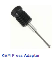
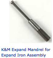
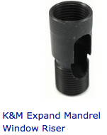
Expand all of your case necks.
Assemble your Neck Turning Lathe and back the cutter adjustment off at least 0.002" from the maximum case neck thickness. Be careful not to allow the cutter adjustment to back out of the body, its a double screw arrangement that will drive you nuts trying to reinstall.
Place the lathe pilot into the the lathe. Attach the jack screw assembly and take up the slack. Insert the pilot into the case mouth (it should be a snug fit), and rotate the case under the cutter until you have located the high spot. Gently advance the cutter until it just touches, then back off a few 0.0001's and tighten the cutter. Rotate the case. With luck you will have landed on the correct setting to just kiss the high spot.
The cutter advances 0.002" per revolution. On the body of the lathe there are 5 marks around 180 degrees giving 1/10 revolution indicators, or 0.0002" per mark.
Slowly advance the cutter, tighten the cutter, turn the neck until you have a spot large enough to measure neck wall thickness. From here on you can try a cut, test a measurement to sneak up on the correct setting. Remember - you want to remove no more than 1/2 of the thickness variation for most applications.
Preferred tool: K&M Neck Turning Lathe and accessories from the K&M Brand page at MidwayUSA (available elsewhere as well).

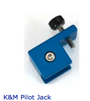
TBD
TBD
TBD
TBD
TBD
Many powders exhibit variations in muzzle velocity that are directly proportional to the ambient temperature, or to the temperature of the ammunition and or the chamber. Some years ago Hodgdon spent some effort on developing powder that now comprise its 'Extreme' line. Other manufacturers have not been so public with their temperature stability. Military snipers develop and use temperature tables for all of their ammunition, and for them it makes a great difference. The military however is not in the handloading business, so the sniper must observe and correct for the effect. As a handloader you can anticipate the effect and compensate for it by component selection, or you can observe it's effect and compensate after the fact. Most powders will generate higher muzzle velocity with warmer conditions - but the occasional powder exhibits an inverted effect. In some powders the difference between warm and cold is enough that if you are developing a hunting load in the summer, it will be all but useless in the winter unless you observe and compensate.
Another place where we need to observe temperature variation could be in some of the measurements we attempt to make that have resolutions smaller than 0.001". Materials change size with temperature significantly. The only thing I want to say about it here, is that when you are neck turning, particularly if you are using a power source to rotate the cutter or the case, you may create enough heat that the result is not to your liking. Light lubrication with sizing wax works wonders.
TBD
TBD - Mfgr, Purpose (SR, LR, SP, LP), Number, Cup Hardness, Brisance, Calhoon Primer Chart,
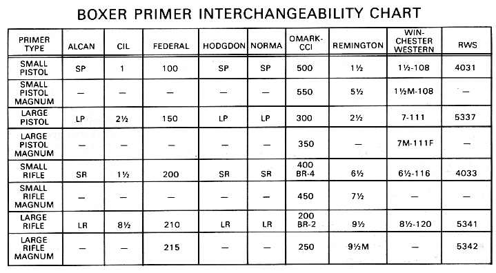
For this discussion we are going to
make several assumptions. To start with, we are only discussing
modern center fire rifle metallic cartridge reloading. We also
assume
you already have a particular rifle and caliber selected. There
are
times when power takes priority over accuracy (for example bear
protection loads), we are going to assume you want your rifle and
ammunition to shoot with more accuracy than power so that you can
hit
what you are shooting at. If you think you need to increase power,
select a cartridge known for excellent long range performance and
limit yourself to ethical ranges, meaning ranges where you have
proven you make ethical shots. Unlike defensive pistol shooting
where
power, accuracy and speed are balanced, we are going to assume you
have all the time in the world to make the shot, and that the
cartridge you have chosen is sufficiently powerful even when using
less than maximum loads. We are going to assume that accuracy is
paramount.
Quick Load is a computer program that calculates
the firing conditions of nearly any cartridge. Quick Load (QL) is
commonly used to find the barrel time (Bt) or the length of time
it
takes the bullet to exit the barrel, muzzle velocity, pressure and
many other parameters useful to engineers and forensic analysts.
Quick Load is relatively inexpensive, and once calibrated to the
specific measurements of your cartridge it makes accurate
predictions.
Determine the purpose of this load. Will it be used for target shooting? Hunting? Defense? Offense? Something Else?
Based on the purpose, select what you believe is the appropriate bullet from among all the bullets available to you for your chosen rifle. For hunting you want to consider the species of game animal, maximum range at which you may shoot the animal, and the environment in which you are likely to be shooting. For long range hunting, make sure the bullet you select will be stabilized by the twist rate of your rifle. Berger and JBM Ballistics offer free on-line stability analysis. Once a bullet has been selected ensure you have a sufficient supply of them. Between testing and training you will likely use up 100 bullets pretty quickly. If you plan to use this load for many years, you should also plan to test, verify and train annually.
There are a lot of factors that might be considered when choosing powder, from availability, to price, and shooting characteristics, that are up to you, but the one immutable fact is that you need to select a powder that will work with the cartridge and bullet you have chosen. Powder burning rate is a measure of the relative speed that a particular powder burns in the cartridge and bore. That translates directly into how fast gas is generated and that translates into how much gas can safely be generated while remaining below the bursting strength of the firearm. Reloading manuals are available from a number of sources but component manufacturers and powder manufacturers are the ones with the resources to investigate a wide range of compatible components. Avoid load recipes you find on the internet, although internet sources are useful for cross-checking ideas you are researching, never rely on someone else's load to work equally well in your rifle.
There are a couple of very important ideas to keep in mind when choosing powder for long range shooting.
The first is temperature sensitivity. Some manufacturers have recently introduced temperature stable powder that behaves very much the same over wide variations in ambient temperature, while others (the older powders mostly), exhibit enough sensitivity to powder that loads you get to work well in summer are useless in winter and vise-versa.
The second is how clean the powder burns. You won't find much about this in loading manuals, even those from the manufacturer. There are two undesirable residual effects of firing, carbon and copper. Some powders just burn cleaner than others, and sometimes they don't burn as clean in larger or smaller cartridges The residual carbon accumulates between shots and eventually accuracy deteriorates. I do not know of any powder that appears to burn dirty that continues to be accurate longer than a clean burning powder. Then there is copper fouling. This happens because some of the copper in the bullet jacket is vaporized by the heat of firing and/or heat of friction. The copper gas then condenses onto the inside of the barrel. Sometimes copper is simply scraped off and subsequent shots scrape more copper into the same place in the barrel. Eventually accuracy suffers, and then you suffer while you try to remove the copper fouling. Recently powders have been introduced which contain a 'decoppering agent' and reports indicate the stuff works. So if you expect to take a lot of shots between cleanings you may be better off with a powder that reduces or eliminates copper fouling.
Another consideration is the style of powder. Generally it comes either as a stick or a ball. Both are very small, but the stick shapes are harder to dispense from many charge dispensers. Ball powder packs much tighter into the case, and is likely to be somewhat more difficult to ignite.
The best accuracy loads are nearly always found at more than 90% fill ratio. When you are choosing a powder don't select one that has it's maximum charge at less than 90% of case capacity if possible.
As with bullets, once you have settled on the powder, make sure you have enough to supply your shooting needs. There are 7,000 grains in a pound. If you load 50 grains per shot, each pound will load no more than 140 shots. Powder generally comes in 1 pound and 8 pound containers. If you buy more than one container, try to get containers that have the same lot number. A 'lot' means a manufacturers run where all of the product comes from one batch of components, one setting of the machines, and one testing of the finished product. Some powders exhibit significant changes between lots. Once you understand the information in this book, you will know how to adjust for lot to lot variations, but it is much better if you can just avoid the problem.
Powder should be stored in its original container, and kept in a cool, dry, dark place. Stored that way, powder should last at least the remainder of your lifetime.
As with bullets and powder, you
should
establish which primer you are selecting for your load. For rifle
primers there are large and small, standard and magnum, and a
recent
category addition 'military'. Primers from a variety of
manufacturers
may demonstrate variations in the ability to initialize the
burning
of your powder. Variations in primer cup thickness and hardness
between manufacturers may demonstrate variations in the ability of
the primer to withstand cartridge loading forces in semi and full
automatic weapons, however these same variations in hardness may
also
translate into the quality and/or quantity of the primer's
explosion
due to the force of firing pin impact.
When you are
researching the load test range (see below), the published
information may contain the primer used. In my experience,
changing
primer manufacturers or style (standard to benchrest for example)
creates a little less variation in group size than changing bullet
seating depth by a few thousandths. Therefore I recommend you pick
a
primer similar to the majority of the loading manual suggested
primers, and proceed from there to the testing phase. Once you
have
achieved the best charge weight, and best seating depth if you
want
to try additional 'uniforming' techniques, you can try changing
primers, or case neck tension, both of which affect initial
conditions before the bullet leaves the mouth of the case.
Magnum
primers are designed to initiate large case volumes, and standard
primers do a good job of initiating volumes up to 30-06 and maybe
a
bit larger.
Keep in mind that the initial conditions inside
the case, chamber, throat and bore of your rifle affect the
development of pressure, which translates into the rate of bullet
acceleration, and muzzle time. You want every shot to behave the
same, and the initial process of lighting the powder and
generating
pressure may not work as planned if the primer explosion generates
enough energy to force the bullet into the rifling before the
powder
starts to burn. That situation creates an excessively large space
for
the powder to start burning in, which slows the process
significantly, and also puts your bullet into a condition requires
the highest pressure to overcome the engraving force. Fortunately
should this occur, it is likely you will recognize it as a very
slight delay between trigger pull and shot/recoil. Sort of a very
fast click-bang.
Only a very heavy roll crimp into a bullet
cannelure stands a chance of resisting a 'too strong' primer
explosion until the burning powder gas production can catch up.
Primers are sensitive to oil such as found in fingerprints.
Under no circumstances should you ever handle a primer by bare
hand
except to throw it away. This is the main reason I always wear
Nitrile gloves while reloading. No greasy fingerprints on cases,
bullets, or primers. On the cases and bullets it's cosmetic, on
the
primers it is the difference between works, and doesn't work.
Don't
allow other grease or oil from the reloading operation anywhere
near
your primers, or the primer pocket of the case.
Once caveat
with regard to primers. If for whatever reason your load
demonstrates
hang-fires or any noticeable lag between the trigger breaking and
the
shot occurring then I would suggest you look to your primers first
then to your powder.
Using all available sources for your cartridge and bullet, record the suggested starting and maximum charge weights of powder. Summarize the maximum in particular. You may find one or two sources suggest a lower maximum charge than others. If that happens I usually go with the powder manufacturers recommendation for maximum.
You may not want to go as low as the
starting charge, unless you have absolutely no experience with
this
cartridge, or components. Experience has taught that the right
load
will be more than 90% of case capacity, although you won't see
this
number published in most loading manuals. NOTE: See the Initial
Physics section for a discussion about 'Primer Output and Initial
Projectile Movement' for more information.
Subtract the
starting load from the maximum load. That's your charge test
range.
Divide your charge test range by a convenient increment number. I
usually use 10 for simplicity. Divide the charge range by the
charge
increment. For example, in the 308 Winchester, 175g bullet, using
Varget powder the manufacturer suggests a starting charge of 42.0
grains and a maximum load of 45.0 grains. If you were to use these
figures: 45.0g-42.0g = 3.0g/10 = 0.3g which will be your charge
test
increment.
To perform an Audette Test, you will load one round
with each of the charges in your test range. In the example, one
each
of 45.0, 45.3, 45.6, 45.9, 46.1 ...
Load several extra at your
minimum and maximum load. One goes in with the Audette Test loads,
one maximum is to fire first to make sure this load is safe in
your
rifle, and one or more of the min and max are to make sure you are
reasonably zeroed at your Audette target, and have sufficient
target
coverage for the entire test range.
NOTE: If the following paragraph
doesn't make sense, pause here, and read my discussion on Initial
Physics
NOTE: I use 'Ladder Test' and 'Audette' test
interchangeably throughout all of these discussions.
Creighton
Audette deserves the credit for figuring a lot of this well before
finite element analysis computer code, or even electronic
chronographs were available.
Since we are trying to launch the
bullet near the peak of the muzzle rise, where slower bullets
point
higher, and faster bullets point lower, you may see the slower
bullets in the Audette test impact the target higher than the
faster
bullets. I suggest you use your maximum test load to zero your
rifle
at the range that you will conduct the ladder test. By testing the
maximum test charge for signs of over pressure (hard extraction,
ejector marks, case head expansion, cratered primers etc.) you
will
know if you should ever fire that charge again. By zeroing (using
the
maximum test charge) at the ladder test range, you will hopefully
keep all of your shots on the target. We don't yet know for sure,
in
your test, if the fast bullets hit higher or lower than the slow
bullets, but by anchoring one end of test string at the middle of
the
target you should be able to keep everything on your target.
Speaking
of targets, I like to use USPSA cardboard targets for most of my
long
range testing. These targets are 18-1/4" wide by 30-1/8"
tall, and have a silhouette shape (head and torso), the front is
cardboard brown, and the back is white so you can select whichever
side is more likely to highlight bullet impacts. I use a Lyman
target
dot (adhesive orange dot 2", 4", 6" etc) in the center
of the USPSA target as an aiming point. At 300 yards, a 2"
target dot is about 0.7 MOA. You could just as easily use a felt
tip
pen to make an aiming point. The USPSA cardboard target is stiff
enough to support its self when stapled to a rigid support on one
edge only, but if its windy you may need a bit more than that.
Here
is an example of a 308 Winchester / VARGET / 175 SMK ladder test.
You
can clearly see that the faster bullets impacted the target lower.
From this you may get an idea how you should setup your ladder
test
target
NOTE: Between shots #10 and #15 in the ladder test
below, there was a total change in muzzle velocity of 56 fps which
should result in a 1.1" vertical change in point of impact, or
about 0.020" per foot per second change in muzzle velocity, with
faster shots hitting higher. The impacts don't line up in a
straight
vertical line evenly spaced out, because the barrel is pointing at
a
slightly different place at the moment the bullet exits the muzzle
due to the vibrations discussed in Initial
Physics. The wind appeared calm at the time of this test,
but had
there been a full value change of 1.0 mph wind it would have moved
the impact 0.6 inches left or right for any shot in this series.
Shot
#14 at 2712 fps striking below each of the three previous (slower)
shots, indicates that the muzzle was bending upward higher when
the
slower shots left the muzzle. This is the velocity variation
cancelling effect we are looking for.
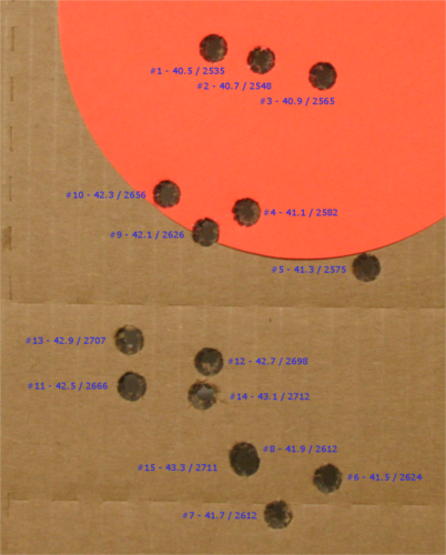
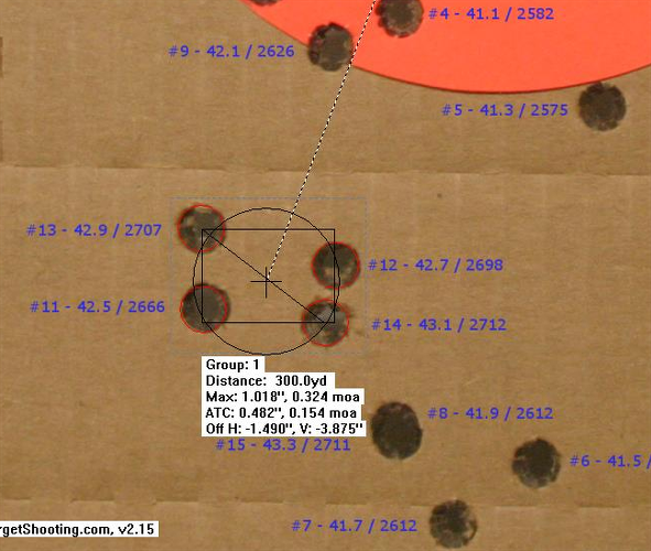
In
this test the charge range was from 40.5 grains to 41.7 grains.
The
test increment was 0.2 grains, and 15 rounds were recorded. Note
that
shot #15 is very close to shot #8. Also note that shots 6,7,8 were
close together but completely out of sequence indicating that
there
was a significant node in this region, however a more desirable
node
occurs between shots #11 and #14 where muzzle velocities between
2666
fps and 2712 fps (46 fps change) impacted within 0.3 MOA.
In this section we are going to necessarily get into a lot of detail about how to take interior measurements of your chamber.
Here is what you need to understand to achieve accurate measurements:
The critical dimension we are trying to measure for bullet seating is the distance from the bolt face to the point in your chamber where the rifling touches your bullet. We will refer to this dimension as Breach Face To Lands (BFTL)
The pointy end of your bullet is where all of the runout goes during manufacturing.
There can be a significant variation in bullet nose length, while all other factors remain constant without affecting accuracy.
The curve of a bullet nose is called its ogive, pronounced: "o-jive", and may be categorized as tangent (spitzer), secant, hybrid and elliptical (or whatever else the manufacturer wants to call it!)
The best place to measure (test) a bullet's length or a loaded cartridges length is from the point on the bullet ogive where it first contacts the rifling to the other end.
Jump is the distance between the point on the bullet ogive where the diameter of the bullet is equal to the (minimum) bore diameter and the point in the barrel where the rifling first touches the bullet.
The critical dimension we trying to measure for headspace is the distance between the breach face and the cartridge case head when the cartridge case is fully forward in the chamber, as it will be at the moment of firing pin impact. Headspace should not exceed 0.007", and should normally be about 0.002" for a fired case.
Bottle neck brass cartridge cases expand radially and axially to completely fill the chamber during firing.
Brass cartridge cases in the 308 and 30-06 class tend to shrink in length by about 0.002" as the pressure returns to normal. They also shrink in diameter a very small amount which is what allows them to be extracted so easily after firing.
Bottle neck brass cartridge cases headspace off of a point called the datum line, half way between the maximum and minimum diameters of the chamber or case shoulder. SAAMI chamber headspace gauge for the 308 Winchester is between 1.640" Max and 1.630" Min, while the case base to datum line dimension is 1.634" Max - 1.627" Min, allowing for between 0.003" and 0.007" end-to-end clearance. The end-to-end clearance is the headspace (space for the head to expand during firing.)
When measuring loaded rounds we will refer seating depth to the distance from the case base to the bullet ogive as CBTO. Keeping in mind that the extractor is likely to hold the case head against the breach, the true zero jump is typically found at CBTO + 0.002" = BFTL for a fired then neck sized case. Full length resizing that 'bumps' the shoulder back must be adjusted so that CBTO + 0.007" <= BFTL or else case head separation at firing is likely to occur. In other words, do not bump the shoulder any more than 0.007" (for 308 and 30-06 cases. Check SAAMI specifications as described above for others).
Many will tell you that best accuracy
occurs when the bullet has zero jump, or is jammed into the
rifling.
This may be more about getting the cartridge into
alignment with
the bore than anything else. When the bullet touches the rifling,
your headspace starts to be controlled by the bullet, and closing
the
breach may well force the case into better alignment. Proper
headspacing, to align the case body without using any force on the
bullet is critical to best accuracy at all shorter seating depths.
Seating your bullet to achieve zero jump seems most likely to generate the highest pressure for a given load, however, according to Quick Load using the 308 example above, the round with the bullet furthest into the case (biggest jump) generates the most pressure. This is due to the smaller initial volume for the gas expand into. I think that may be true however Quick Load does not know the distance to the rifling, so it assumes there is an equal force required to overcome bullet inertia, neck tension, engrave the bullet to the rifling and start the bullet rotating for all cases. It does seem that a bullet given a running start before encountering rifling would present less resistance, but you need to remember the scale of energies involved, and that difference between "dead lift" and "running start" while it appears substantial, may well be insignificant when compared to the force created by chamber pressure. Personally I think zero jump may increase the rate of initial pressure rise and may help to stabilize maximum pressure time, both beneficial to low muzzle velocity variation.
In the Quick Load prediction for the 308 test with the bullet seated furthest out (to zero jump in my rifle) at 2.879 COAL (Cartridge Over All Length) the MV is 2676 at 52,842 psi. For each 0.010" the bullet is seated deeper into the case, the velocity rises by an average of 3.83 fps, and pressure increases by an average of 416 psi. Most importantly however the Barrel Time decreases by an average of 3.8 Milliseconds (mS). Measured MV averaged 3.0 fps faster per 0.010" deeper seating.
Seating a bullet far enough out to touch the rifling in some firearms will make the bullet too long to work through the magazine or the action. Seating the bullet just a tiny fraction further out may cause the bullet to stick in the barrel if a round is unloaded, leaving you with a mess of unburned powder throughout your action and probably preventing you from loading or firing the next round.
For hunters, competitive marksmen and tactical operators magazine function is critical so they would start testing at the maximum COAL that will work reliably in their magazine. Some hunters and marksmen using single shot rifles will want to start with the bullet touching the rifling.
Now that we know all this, I believe the best way to perform an Audette Test is to seat the bullet at the maximum COAL that you will use.
In order to make the adjustments to
your bullet seating die, you need to know the interior dimensions
of
your rifle's chamber. In particular, you need to know the distance
from the breach face (bolt face) to the origin of rifling. When we
talk about bore diameter, we are referring to the diameter of the
lands not the groves. The nose shape of your selected bullet puts
the
location where the bullet diameter is equal to the bore diameter
somewhere between the nose and it's maximum diameter. It is that
point from which all meaningful measurements must be taken. This
point may be found by inserting the point of your selected bullet
squarely into a hole exactly equal to the bore diameter. In fact a
useful measurement may be taken by using a hole only somewhat
equal
to the bore diameter provided that this exact same hole is always
used for this measurement of this bore and bullet. In other words,
there is enough difference in dimensional tolerance between
measuring
tools that you should only have one tool to use for all of your
measurements. If you want to relate your measurements to someone
else
they must calibrate their tool to yours. Have them measure one of
your bullets, cases or loaded rounds, where you have supplied your
measured values. They can then determine the difference between
your
tool and theirs and apply that information where necessary to
achieve
similar results. To complicate matters even further the area of
your
chamber called the leade transitions into the rifled bore with a
structure known as the forcing cone, a chamfer at the beginning of
the rifled bore. Your bullets nose shape intersects the forcing
cone
at some point which is determined by the slope of the cone and the
slope of the bullet nose.
To find the interior dimension
(breach to lands) several tools have been introduced. My personal
favorite was a dummy round that comes with the RCBS Precision
Micrometer kit. The dummy bullet is steel, and has a fairly rapid
transition to the maximum diameter which helps keep it from
sticking
in the barrel. However I have found it necessary to lightly
lubricate
the dummy bullet nose on many occasions. The dummy cartridge body
is
designed to allow the dummy bullet to side in and out, and a
tension
adjustment screw allows for a convenient 'just right' setting. The
dummy cartridge head however is not the same shape as a normal
cartridge case head and sometimes requires a bit of finesse To use
the RCBS tool, the dummy bullet is pulled out of the dummy case
enough that it must be too long, the dummy round is inserted into
the
action (hooked under the extractor and pushed against the ejector)
and the action is gently and fully closed, forcing the dummy
bullet
into the dummy case. If care is taken to ease the action closed
the
reading will be very accurate and consistent. In push feed bolt
action rifles, the extractor and ejector can alter the reading.
The
extractor requires a push on the bolt to snap over the cartridge
rim,
and can push the dummy bullet too far into the dummy case. The
ejector places a strong sideways thrust onto the cartridge to
ensure
the case snaps out of the action as soon as possible. In
controlled
round actions (Mauser) the extractor must pick the case rim up
from
the magazine - it doesn't snap over the rim very well. The ejector
however does not affect the dummy round.
In a push-feed
action; with the bolt open and the muzzle pointed upward, place
the
rim of the dummy case head under the extractor, this may require
the
use of a tool like an allen wrench to help hold the case head
under
the extractor while you use a finger to press the dummy round into
line with chamber against ejector pressure. Carefully move the
bolt
forward while holding the dummy round in line as long as possible,
then carefully close the bolt fully to squeeze the dummy round to
exactly the length between the bolt face and the origin of the
rifling. Carefully open the bolt and retrieve the dummy round
without
letting it be forcefully ejected. With a little practice this is
quick and easy to do.
The second step is to measure the
distance from the dummy round case head to the dummy round bullet
at
the diameter of the bore. This can be accomplished with the
supplied
RCBS tool, but I have found that for this measurement a set of
adapters for a dial or digital caliper jaw are far superior.
Hornady
makes such a tool and with one simple modification it is as
perfect a
tool as I've ever used for this purpose.
The jaw adapter is
installed on your calipers, and an adapter with a hole diameter of
approximately your bore diameter is installed in it so that the
bullet nose can be inserted in the hole, and the distance from
that
point on the dummy or real bullet to the case base is read on the
caliper. This is one place a digital caliper really becomes useful
because it can be zeroed with the jaws closed on all these
adapters,
and then provide you with a direct measurement. Otherwise you've
got
some subtracting to do.
The modification I mentioned is to the
anvil jaw adapter which as it comes from the factory is just a
flat
surface a bit larger than most case heads. I found that fired
primers
often had ridges around the firing pin impact that changed the
readings using this anvil by several thousandths of an inch. Using
the bare jaw, the caliper still 'sees' the ridges. To correct the
problem, I took a 1/4 inch washer that appeared to be fairly flat,
drilled out the center a bit so it is larger than any primer, then
stoned it flat on a coarse diamond bench stone on both sides, and
tested it with a micrometer to ensure its sides are parallel. Then
I
stuck the washer onto the center of the anvil with double sided
tape.
Its been on there working perfectly for over a year now. And yes
that
adapter is easily zeroed out too. Now I get very consistent
readings
on cases regardless if fired, primed, sized or loaded.
A last
quick note about the Hornady adapter. They also provide holes
sized
for cartridge case shoulders allowing you to take precise CBTD
(Case
Base To Datum) readings, to use while adjusting your dies to
minimally work the case for much better fit and longevity.
Another
tool that you could use is called a 'bullet comparator'. It is a
block of aluminum or steel that has holes drilled through each
side
for various caliber bore diameters. The block is often just 1.000"
from side to side regardless which side, simplifying your
calibration. It is used the same way, by placing the bullet end
into
the appropriate hole and measuring the length, the subtracting the
length of the comparator
Hornady and others have introduced a
tool which uses a cartridge case on a push rod to position a case
and
a bullet in the chamber, extend the bullet until resistance is
felt,
then lock the bullet push rod in place to facilitate measurement.
This tool can not give you an accurate measurement to the bolt
face,
but it can give you an accurate measurement from the bullet ogive
to
the case shoulder datum line. Keep in mind that the modified
cartridge case supplied with the tool was not fired in your
chamber,
so its headspace relationship can be in the range 0.003" to
0.007" different than your actual headspace. One way to fix the
problem is to make your own modified case from one fired in your
chamber. Another is to measure the CBTD of the modified case, and
a
fired case to calibrate the modified case to your chamber. It is
necessary to calibrate the supplied 'modified case' to your fired
(and resized case) so that you can use the resulting measurements
to
accurately measure and adjust loaded rounds. In all cases remember
that a case fired in your chamber will shrink in length so it is
not
a perfect measurement, but might be within 0.002" or so. Also
please note that the instructions that come with the Hornady
Lock-N-Load OAL gauge appear to exhibit a fundamental flaw in
understanding how the comparator works. Variations in bullet nose
shapes between different types of bullets do move their datum line
(point where the bullet diameter equals bore diameter) forward and
backward with respect to your reference bullet, however it is that
very datum line we are measuring, and the amount of bullet nose
protruding forward of the datum line is only important to magazine
function. The RCBS (and other) dummy bullets may have very abrupt
nose shapes but that ensures the datum line is consistent. Unlike
the
Lock-N-Load dummy rounds the RCBS tool reads from the breach face.
There is no 'source of error' due to nose shape. Ever.
Others
have used the idea of a rod inserted in the bore from the muzzle
to
find the position of the bullet in the chamber. This measurement
technique can produce accurate and repeatable results, for BFTL.
Since the case is forced back toward the bolt face during
measurement, this technique can not accurately utilize the
shoulder
datum as a reference point potentially introducing errors up to
0.007". This technique must NEVER be used on loaded
ammunition.
Because as I showed you earlier on, a difference
of just 0.010" can cause a significant change in velocity,
pressure and barrel time, your measurements must be consistently
accurate to 0.001" to be meaningful.
One last note; The
RCBS Precision Mic dummy bullet will give Breach Face To Origin of
Rifling measurements in any type of action be it bolt, falling
block,
break open or anything else. The Hornady tool discussed above can
make its measurement in many action types, but has one continuous
disadvantage in that you can never close the action on the tool,
thus
the measurement is Case Head To Origin Of Lands, referenced off of
the case datum line, and you need to add in the Headspace for the
test cartridge case to get Breach Face To Origin of Lands. Or you
can
just forget about the roughly 0.002" headspace of a fired case
and go with Case Head To Origin Of Lands all the time. Just
realize
the measurement (using bottle neck cases) will be based on the
case
shoulder datum line rather than the breach face (case head +
spring
back). Make sure your case actually enters the chamber all the
way.
Often the extractor will hold the case head against the bolt and
the
case shoulder may be out of contact with the chamber. In break
open
rifles i.e. T/C Contenders and Encores remove the extractor to
make
the measurement.
Having defined the test charge range, and increment, load one round with each charge.
Having determined the dimension for a zero jump bullet seating depth, choose the minimum seating depth (maximum length) that you will use. If you are using a magazine it will be the maximum length that feeds reliably from that magazine. Otherwise either zero or 0.010" jump is appropriate.
Seat all test rounds to the same depth.
Load a few fouling rounds with the maximum charge used in the test. Use these rounds to foul and zero your rifle just prior to the test.
Setup a large target. I use IDPA target with a 2" aiming point about 3/4 of the way up from the bottom. The aiming point must be visible at 300 yards, and not too large to aim at accurately. The right size will depend on your sights more than anything. Make sure there are no holes in your target (that haven't been pasted).
Place the target at 300 yards from your firing point.
Place a fouling and zeroing target at the same range near your test target.
Using the fouling and zeroing rounds adjust your sights until you are hitting near your aiming point with the maximum test load charge.
Now that the rifle is warmed up, and the barrel is fouled, fire each of the test rounds in charge increment sequence at your test target. Always aim at your aiming point regardless where the rounds strike. As you fire each round record its position on the target. This is critical. You MUST know the charge that resulted in each hole in the target.
Number or otherwise mark each hole once you have retrieved your target.
There will be vertical stringing of your shots. Ok, I had one test with a Ruger SR-556 in 5.56 NATO that clustered all 10 shots in one ragged hole in this test. I think that must be due to the very short stiff barrel. It means that I can load nearly anything in that rifle and it will shoot where I point it.
Back to the test. Recall how in Initial Physics I described the motion of the barrel with the muzzle pointing away from the centerline of the barrel while the bullet is still inside the bore? You just mapped that motion in your barrel over the time between the shortest and longest barrel times in your test. By 'mapped' I mean your barrel was vibrating around the same way for each shot, but each shot took a little bit different time to get out of the muzzle, so each shot 'points to' where the muzzle was pointed at that moment. If you connect the shots with a line, and smooth it out, you probably will get a very accurate map of your muzzle vibration.
What we are interested in is just one part of that map. The part where two or more shots hit at nearly the same elevation, or even better where several shots hit close together. These points on your muzzle map indicate the times when the sum of the vibrations is lowest. Since the vertical vibration has the greatest amplitude, selecting shots at the same elevation regardless of horizontal separation should locate the charge (hence the pressure, velocity or barrel time) that causes the bullet to exit when the vertical vibration is moving slowest. Having a hard time with that? Any vibration in a single plane must come to rest at some point before reversing direction. We are looking for that point.
Find the middle of the charges that resulted in vertically close impacts. This is the charge you will use from now on with these components.
As I showed you previously changing seating depth changes pressure, velocity and barrel time. By testing changes in seating depth you should find that your groups shrink dramatically at one or more depths.
I use 5 shot groups for all of my group testing, but 3 shot groups might be adequate for initial testing.
Using the selected charge from the Audette Test, load however many you are going to use for each group by seating depth.
Having started at the maximum COAL you will use, you only need to seat bullets deeper for each test. I typically run the first seating depth test from the Audette Test depth to an additional 0.060" by 0.010". However some bullet nose types (Berger VLD's for example) have a defined range of 'sweet spots' - see manufacturer for more information.
Clean your rifle. After the Audette Test the rifle is to dirty to complete the group testing without cleaning which will alter results. Fire 3 to 5 shots to zero at 100 yards, and foul your rifle Don't shoot more than about 30 more shots before cleaning and re-fouling while group testing. It helps to zero your rifle so the impact point is about 1" high so you don't obliterate your aiming point in the following tests.
With the rifle warmed up and fouled, at 100 yards fire each seating depth at its own target. One of these targets should exhibit a significantly smaller group than the others, and if you are lucky the targets before and after that one will be only slightly larger with a clear indication that group size is shrinking as seating depth approaches the best group. With that information you may be able to determine that a second seating depth test with increments of 0.003" would be useful to determine the very best seating depth.
The '6.5 Guys' youtube video describing their method of working up loads describes looking for flat spots in the velocity curve between test charges. They observed that the SD (Standard Deviation) of the shots falling on these flat spots was lower than the other shots in their test. In working up a load for my 6.5 Creedmoor I encountered a similar situation where group size was not changing with seating depth enough to make a determination, but the SD for 3 shot groups was an obvious indicator. When I located one seating depth with a very low SD, I set 5 additional shots to the same CBTO and found the low SD to be repeatable, and group size was acceptable. For long range shooting downrange performance can be affected more by velocity variation than by shot dispersion, so 'good' groups at 'single digit' SD's may be preferable to 'excellent' groups with 'double digit' SD's.
From your best seating depth group determine the inherent accuracy of this load in that rifle in terms of MOA. Measure the center to center distance of the widest shots in the group. For our purposes 1.000" = 1 MOA at 100 yards. If you want to use more precision 1.047" = 1 MOA at 100 yards. Knowing the MOA capability of your load allows you to predict its performance at other ranges. For example if you made a 1 MOA group at 100 yards (1 inch) then at 300 yards you should be able to shoot a 3 inch group. If you made a 3/4 MOA group at 100 yds, then you should expect about 0.75 X 3 = 2.25 inches.
Now that you have established the best charge weight and seating depth for your selected components, and know about what group size to expect at longer range confirm that your load is 'pressure tolerant' (or velocity or barrel time tolerant), by loading one round with the chosen charge, and one round with 0.1g more and another with 0.1g less powder. Seat all three bullets to the chosen seating depth.
Fire a group at 300 yards with these three test rounds. In the vast majority of cases, all three shots will strike inside the inherent accuracy of this load in your rifle.
Congratulations, you have just found "The Right Load" in 10 shots for the Audette Test, and 21 or 35 shots for the Seating Depth Test a total of at most 45 test shots and a few zeroing and fouling shots, while a lot of your friends may have fired hundreds of shots randomly seeking 'good groups'. With the information you have collected in your first test, you may be able to cut the range of test charges, and seating depth test if you choose to change components, allowing you to develop loads quickly and efficiently when sources of your favorite components dry up, or new components become available.
If you have or choose to use 'conventional' dies (7/8" x 24 tpi screw-in dies), you can still produce excellent reloaded ammunition, but you are going to need to pay attention to, and correct for the flaws inherent in that style die.
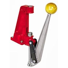
Suitable for all 'normal' reloading tasks, provide excellent access, inexpensive, moderately durable. The alignment between the ram and the die station is often quite flexible (not a good thing). Leverage is not high in this style press. The Lee hand press (on the right) is portable and uses the same dies as your bench press.
Suitable for more difficult reloading operations such as making cases for one cartridge from another, primer pocket swaging, bullet swaging (usually accomplished on smaller dedicated equipment). Only has one die position, performs most operations one-at-a-time except priming (if you use the on-board primer system), in other words you do each step to all of the available cases, then sometimes reconfigure the press, replace the die and perform the next step, etc. until done. These presses are so durable that used equipment is often just as good as new. This type of press often exhibits a high degree of alignment between the ram and the die station, and has little flex under load. Leverage is typically very high in this style of press.
These
presses qualify as 'Open Style' for strength, and has provisions
for
several dies installed in a rotating holder. Allows you to quickly
load one round from beginning to end, by rotating dies into
position
above the ram. Also permits very fast change between dies to speed
up
batch reloading. This design exhibits some flexability. Not
recommended for high pressure use. Leverage is typically moderate
to
high.
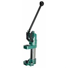
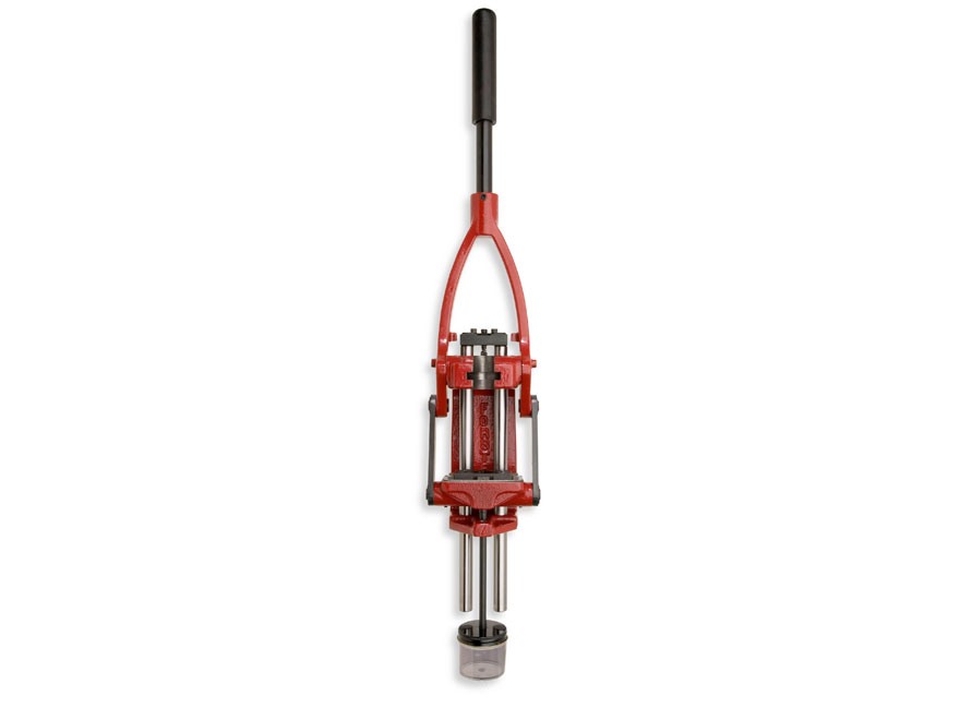
Bonanza
and RCBS produce presses that operate with a downward action and
include a floating die holder that automatically aligns with the
case. This also happens in an open or 'O' press with the die at
the
top but to a lesser degree. These inverted in-line presses are
typically quite strong, however operations such as primer pocket
swaging don't lend themselves to inversion very well.
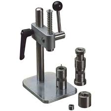
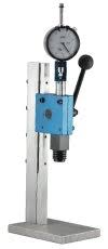
This
style of press does not supply very much force at all, but it is
very
small and light weight, travels well, and is the choice of many
benchrest shooters for accuracy (mostly because of the dies they
use). If you choose to start out on an arbor press, you will find
at
some (usually early) point that you also need a conventional
press. I
recommend a used 'O' press to perform those occasional tasks that
an
arbor press can not, for example primer pocket swaging, and case
forming. Arbor presses do not generate enough force to partially
or
fully resize the body of the case and so the dies they use are
exclusively bushing type neck sizer. Speed of reloading is a
little
faster than using an open or 'O' press, but way slower than a
turret
or progressive press. Case preparation, mostly turning the case
neck
to a uniform thickness increases the precision of these dies
substantially.
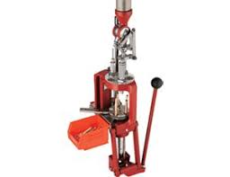
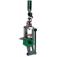
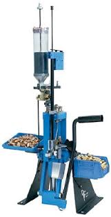
This
is the high volume 'king of quantity'. There is no question that
progressive presses can produce match quality ammunition, and
depending on how much you want to spend they can automate
everything
so all you have to do (after tuning it) is load up the hoppers,
flip
the switch and then make sure the hoppers stay full until you run
out
of supplies or money. When I was shooting NRA Handgun Silhouette
in
the late 1980's I used a Hornady progressive press to load between
2
and 3 thousand rounds of 357 Magnum and 44 Magnum per month, to
keep
several shooters supplied. Current production (2015) Dillon
progressives can do that in less time than it takes to explain it.
Case Sizing - Return the fired case to usable dimensions suitable
to
be loaded and fired.
Full Length Sizing - Returns the neck,
shoulder and body to dimensions well within SAAMI specifications
so
that the reloaded round will function in any properly reamed
chamber.
Neck Sizing - Returns only the neck dimensions to
specifications suitable for loading. Cases so sized are to be
fired
ONLY in the chamber that last fired the case. Neck sizing does the
least damage to the case, and is typically used to extend the
reloading life of the case. It also causes the bullet to present
to
the barrel in the most concentric position, enhancing accuracy.
Getting neck sizing 'just right' for accuracy is an advanced
reloading topic.
Competition or Small-Base Die Sizing -
Partial body resizing to ensure smooth operation in semi-automatic
actions. Also sizes neck and shoulder dimensions.
Carbide Die
Sizing - Straight walled cases, such as typical pistol and
revolvers
use can be sized using a die with a carbide insert. The use of
carbide eliminates the need to lubricate the case prior to sizing,
and is most useful for production loading on a progressive press.
If
you think you might get into volume reloading for a cartridge that
can be resized with carbide it will save money to get these
expensive
dies first and skip buying cheaper dies to learn on.
Priming
- Replacing the expended primer with a fresh primer. Many (if not
all) presses come with some form of priming ability. Never the
less,
many reloaders prefer to use a separate hand press to dispense and
install primers. These hand presses provide more 'feel' for the
priming operation, and they can be made to work at a speed that
keeps
many of us happy. I will discuss hand priming later when we get
into
accuracy issues. For now all you really need to know is that your
fingerprint is a sufficient amount of oil to degrade a primer over
time, so you really don't want to use a method of priming that
requires you to pick up primers by hand (or else wear nitrile
gloves
- which I do nearly all the time while reloading anyway).
Primer
Pocket Swaging - Military brass (which is often very inexpensive)
typically has its primer crimped into the case, and may also have
a
sealer (typically a lacquer). To make the case usable for
reloading,
the crimp must be removed. Can be accomplished by swaging (forming
under high pressure), or reaming (cutting). Swaging is the
preferred
method most of the time, as it leaves a nice smooth, slightly
rounded
entry, and ensures there are no small pocket diameters. Requires a
significant amount of force applied to the press handle, in both
directions. Lubrication of the primer pocket and the die is
necessary, and you should be meticulous about removing the
lubrication before priming the case, as any oil (or other foreign
material), may affect the efficacy of the primer, particularly
when
the loaded round is stored for extended periods.
Bullet
Seating - The neck of the case has been sized so the inside
diameter
is about 0.002" smaller than the outside diameter of the bullet,
the case has been primed, and powder has been installed. The next
step is to press a bullet into the fragile neck of the case (when
you've broken as many as I have they are fragile!)
For
accurate rifle cartridges, the distance you force the bullet down
into the case (as measured from the base of the case to the
circumference of the bullet at the diameter of the lands in the
barrel) must be repeatable to 0.001". If your press exhibits any
spring (stretch), you may have difficulty with maintaining
accurate
bullet seating - this is another area where the Arbor press and
hand
die excel at maintaining concentricity, and repeatable bullet
seating.
Neck Crimping - To prevent bullets from moving in
the case neck when they are subject to recoil (in the magazine),
or
to improve velocity consistency you may crimp the case neck into
the
bullet. This operation generally does not require much force. As a
matter of fact, a typical "O" press generates far too much
force for this operation to be controlled accurately by feel.
Bullets loaded
for
heavy recoiling pistols and rifles generally have a ring swaged
around the bullet where the manufacturer suggests the case mouth
should be centered after the bullet is fully seated. Most pistol
and
many rifle dies have a built in roll-crimp that can squeeze the
mouth
of the case into this area. Getting this crimp right requires
getting
the case length right, as well as getting the die installed in the
press to just the right depth at the same time that the bullet
seating punch is adjusted just right to seat the bullet. The
benefit
of this type of crimp is that the bullet is very firmly held in
the
case neck and is unlikely to ever come loose for any reason until
it
is fired. Typically the applications that use this technique do
not
achieve the highest degree of accuracy, however these dies can
also
be adjusted to not crimp.
Most semi-automatic pistols use a
rimless cartridge that headspaces off the case mouth. This type of
ammunition must never be neck crimped, as it is likely to
negatively
affect reliability. The firing pin strike may push the case
further
into the chamber to the point where firing pin can no longer
ignite
the primer causing a mis-fire, because the case mouth did not
engage
the chamber correctly. These types of cartridges use a straight
crimp, and their seating dies generally do not have the ability to
crimp the case mouth into the bullet.
NOTE: This applies only to accurate rifles. Accuracy requires the gas pressure generation to occur at very consistent rates. As gas is generated, the volume the gas can occupy dictates pressure, which in turn dictates the burn rate, which closes the loop by dictating the gas generation rate. The bullet weight, distance to the rifling and neck tension all affect the initial burn rate and thus the initial conditions for the shot. By adjusting neck tension we may be able to slightly retard the movement of the bullet in the very first few microseconds, causing the gas pressure to climb more quickly and then as the bullet moves into the rifling there is more pressure available to engrave the bullet to the rifling and that improves consistency, and thus accuracy.
UPDATE: According to Aberdeen Proving Ground, the presence or absence of rifling makes no difference to bullet position, pressure, or pressure generation. Thus the most likely major factor retarding the acceleration of the bullet is the mass of the bullet, and the friction of the barrel.
This type of crimping is more
difficult to achieve, and requires precise measurements of the
case
neck wall thickness, (and neck turning to make neck wall thickness
uniform), combined with the use of 'bushing' type neck sizing
dies.
Typically bushings are selected to size the neck inside diameter
to
be 0.002" smaller than the bullet diameter. This is achieved by
changing the part of the die that resizes the neck (bushings).
Generally they are available in 0.002" increments, and are
easily changed.
This technique is most often used with a hand
die and an arbor press. Recently several manufacturers of
conventional dies have offered bushing dies.
One very large
advantage of using this method has to do with maintaining
concentricity between the chamber, case and bullet. In
conventional
dies, the fired case is run into the decapping/resizing die, and
as
the case is forced further into the die, the neck is resized from
the
outside to a diameter that is far too small. At this point, the
outside of the case neck is concentric to the outside of the case
body, and any neck wall thickness variation has been forced to the
inside. Then as the case is removed from the die, a ball on the
decapping stem is drawn through the neck to achieve the final
inside
diameter. If the neck wall thickness was not uniform to start with
(and most untreated cases have a few thousandths variation), that
error is now forcing the case neck off the center line of the
case,
and the force of the ball reforming the inside diameter is also
drawing the neck and shoulder forward in a way that can contribute
to
a lack of concentricity because the shoulder and neck are no
longer
supported by the die.
The difference in accuracy between
techniques can be measured in the difference in concentricity of
rounds produced by each. For hunting and short range work
conventional dies are easy to operate, and produce adequate
accuracy.
If you are interested in high accuracy then you should plan
to use an arbor press and hand dies featuring changeable bushings,
and you should equip your reloading bench to accurately measure
neck
wall thickness, and to turn case necks accurately to remove or
reduce
wall thickness variations. Neck turning is preformed on each case
just once, and adds significant potential to achieving the very
best
accuracy your rifle is capable of.
Many conventional seating dies are designed to apply a crimp to the top of the neck of the case at the very last bit of the case's movement into the die. This type of crimping is appropriate for bullets with a cannelure (a grove around the bullet), and mostly reserved for heavy recoiling or hunting applications.
Rather than use the built-in crimp on
your bullet seating die, you can use another die (usually a collet
type die), to squeeze the case neck into the bullet.
There are
a few advantages to doing it this way. First separating the
crimping
from the seating prevents crushing which happens all too often,
and
ruins the round. Crushing happens because the crimping action
occurs
during the last few hundredths of an inch of travel as the bullet
is
being seated into the case. Two things are happening at the same
time, as the bullet is still moving into the case while the case
is
being squeezed into the bullet. Second, the amount of crimping
force
can be controlled very accurately. In addition the amount of crimp
that can be applied this way is very much greater, to the point
that
the case neck can be forced into a bullet that was never designed
to
be crimped!
In my accuracy testing (which was not particularly
extensive) I did not find that using a collet crimp increased
accuracy over controlling neck tension by neck turning, and I
expect
that from here on I will continue to use neck tension adjustment
by
turning exclusively for accurate ammunition.
On the other
hand, using a collet crimping die on any hunting, or tactical
bullet
may be the best way to ensure that the ammunition system works
flawlessly.
For me this part is mostly
theoretical
as I haven't done any casting myself, and the last time I watched
anyone do it, was four decades ago. With all the 'new' information
about lead vapor and dust health hazards, I'm fairly certain I'm
not
going there unless I have to. Regardless, here is what I know
about
the subject.
You can melt lead with a wood fire, or anything
hotter. You can get lead from old pipes, wheel weights, bullet
traps,
and a myriad of other sources.
Use a cast iron mould to cast
the bullet. You pre-heat the mould by letting it float on the pot
of
molten lead for a little while. You need to flux the molten lead
to
get pure lead into your ladle. Very carefully fill the mould with
molten bullet lead, make sure you fill the cavity completely.
Leave
the 'sprue cutter' open until the lead freezes, then use it to cut
the sprue (the excess lead) off of the casting, then open the
mould
and dump the bullet onto a place to cool. Repeat until you are
done.
Moulds come in every caliber, shape and weight imaginable. You
could
easily make your own mould from steel if you have a few simple
tools
like a dill press.
Once you have a cast bullet, it needs to be
forced through a die that will make the outside diameter exactly
correct. Typically these presses and dies are dedicated tools. The
sizing die typically also performs the lubrication step. Lead
bullets
tend to leave some of themselves in the barrel, especially when
they
are fired at over 1,000 fps. Changing the recipe for the lead
alloy
to something harder than pure lead and adding a grease grove,
filled
with grease are the techniques typically employed. The grease can
be
forced into the grease grove during operation.
The grease can
be anything from animal fat (causes rust nearly immediately due to
the salt content), to synthetic grease that is easy to handle and
doesn't come off on your hands when you are loading. That's the
blue
stuff you'll see if cast lead bullets you may buy in bulk.
In the early days of varmint hunting with centerfire rifles (early 20th century), jacketed bullets were necessary to reduce fouling, but were very expensive, and often not available. The 22 Long Rifle case is a single use case because it's a rimfire, and someone figured out that you could put a bit of lead wire and a fired 22LR case into a die and get a pretty useable jacketed bullet out of it, and bullet swaging (at the reloading bench) was born. It also is the real reason for the "O" style press, the extra strength and mechanical advantage of the ram linkage is required to achieve the force necessary to reform brass and lead without destroying the press. Today the only people who appear to be messing with bullet swaging are benchrest shooters, and recently Walt Berger started producing high accuracy swaged bullets (using the very technique described above), with extremely precise copper jackets to turn a reloading press just like yours and mine into a multi-million dollar bullet business. Most folks would rather buy the bullet from someone else than do the work necessary to swage their own, but the dies, materials, and tools are available if you want to try it.
As you look at the bewildering array of available calibers, cartridges and bullets you may not be aware that nearly all were the result of shooters not much different than you, who wanted something 'special'. Manufacturing a brass cartridge case from scratch is much to complex and expensive for hobby or experimental reloading. Since there are so many different case designs already in factory production, it is very common to use an existing cartridge case as the starting point for a new idea. When you design a new cartridge the process is called 'wildcatting' and the resulting cartridge is called a 'wildcat'. One of the simplest wildcat operations is to change the neck diameter of a factory cartridge to accommodate a different bullet. For example the 25-06 was created by Charles Newton in 1912 by changing the neck of a 30-06 to accept 25 caliber bullets. The 25-06 was released as a factory round by Remington in 1969. There are a number of case forming operations you can perform with a good 'O' style press.
In order to load precision ammunition you will need a method of measuring the amount of smokeless powder to be used. Although volume measurement can be accurate, weight measurement is uniformly recognized as the best means of accurate powder charge measurement. For reloading the unit of weight measurement in common use is the grain. There are precisely 7,000 grains in one pound. 1 gr (grain) is equal to 0.06479891 g (grams). Often gn is used as the unit indicator for grains. All modern reloading scales are calibrated in grains, and all modern reloading manuals reference charge weights to grains. Scales are available in balance beam and electronic types. The balance beam is very accurate, but quite slow whereas the electronic is fast put prone to measurement errors due to amplifier drift in the sensor electronics. Electronic scales can be connected to motorized powder dispensers. Such powder dispensers can be run to quickly dispense very precisely measured powder charges, but should be checked periodically against either a balance beam scale, or check weights.
Balance beam and electronic scales can both be used with an accessory powder trickler, a small powder hopper that is operated by hand to dispense powder very slowly, so as to trickle the charge just up to the desired weight, a very intensive and time consuming process, that achieves high accuracy. Volume measurements of reasonable accuracy can be achieved using a device that 'throws' a powder charge by filling a chamber, the volume of which can be controlled. Ball powders lend themselves readily to dispensing via volume measuring devices because the shape of the power kernel allows it to pack densely with little agitation. Stick powders on the other hand, often jamb the mechanism of volumetric dispensers and cause wild swings in dispensed load weight. In general, accurate loads will have powder weight uniformity within +/- 0.1 grains.
When bottleneck rifle cases are
forced
into a full length resizing die to return their outside dimensions
to
a standard suitable for all actions of the caliber, the brass will
flow toward the neck of the case, causing the case length to
increase. When the case neck length has increased to the point
where
it interferes between the chamber and the bullet, it is possible
to
wedge the bullet in place such that at firing pressure exceeds the
bursting strength of the barrel. The solution is to trim the case
neck length to be well within the length established by the
chamber
drawing. The Sporting Arms And Manufacturers Institute (SAAMI) is
the
clearing house for cartridge and chamber dimensions and they
provide
dimensioned drawings reloaders refer to for critical dimensions.
You
should be in possession of the drawings for every cartridge you
reload.
When you utilize only bushing style neck sizing of cases
fired in the same chamber, you will find that the neck length does
not grow, and that many resizings can result in little to no need
to
trim case length. That said, you should confirm this with each
case,
every time you reload it. A chamber gauge is very useful for this
task.
Recent questions and comments in several reloading forums have prompted me to get curious about the effect of neck trimming to maintain case length.
Many people feel it is necessary to hold tolerance for COAL (Case Over All Length) to something like 0.005”. How important is that really?
Straight wall cartridges headspace off the case rim and typically are crimped using a roll crimp in the seater die. In this situation case uniformity results in similar crimps in each round – a good thing. The amount of variation in case length probably is only significant if case length becomes shorter (or longer) than about ½ of the roll semi-circumference (the distance from the case mouth to the point on the case where there is no crimp). That should provide a rough guideline for roll crimps – keeping case length to +/- 0.005 seems reasonable.
Bottleneck cartridges headspace off the shoulder and are typically crimped best with a roll crimp only when the bullet has a cannelure.
For bullets without cannelure, a 'straight crimp' or a 'factory crimp' are options that squeeze the case neck without producing a roll in the case neck.
The straight crimp is a tapered section within a seating die that engages the case at the moment the bullet is nearly fully seated and squeezes the neck during the last few thousandths of case travel. If case neck length varies the crimping action may begin sooner than desired and bullet seating uniformity suffers, or bullets and cases can be destroyed in severely mis-adjusted dies.
The factory crimp is applied by a collet die as a separate step. The collet is squeezed into the case neck based on the position of the case shoulder, and neck length has no bearing on the crimp.
So, what is the effect on exterior ballistics due to changing the case case length?
Lets take a look using QuickLoad to analyae the effect of changing trim length by 0.001, 0.005 and 0.010 inches. I'll use the .224" 55 grain Armscor FMJBT bullet, 223 Rem (SAAMI) Cartridge and 28.1 grains of Hodgdon CFE-223 powder which calculates to 54,937 PSI and 3005 fps at the muzzle. The bullet would take 0.766 mSec (1 mSec = 1/1,000 second) to travel from 10% Pmax to the muzzle when the case is at a trim length of 1.759".
Changing the case length to 1.750" changed the pressure to 54,491 psi, MV to 2999 fps, and Barrel Time to 0.769 mSec (3 uSec slower).
Changing the case length to 1.740" changed the pressure to 53,975 psiI, MV to 2992 fps, and Barrel Time to 0.772 mSec (3 uSec slower).
Changing the case length to 1.730" changed the pressure to 53,492 psi, MV to 2985 fps, and Barrel Time to 0.776 mSec (4 uSec slower).
Next, I took the velocity data to JBM Ballistics to obtain drop data for a 100 yard zero over 1,000 yards by 100 yard increments and constructed the following table:
As you can see, changing the case length by 0.010 more than its SAAMI range of (1.760 -0.030) we see a difference in MV 28 fps which results in a difference of POI (Point of Impact) of 13 inches at 1,000 yards, or 1.2 MOA. Or to put this another way, for each 0.001 change in case length there is a 0.325” change in POI at 1000 yards.
So keeping case neck length or case over all length in a tight tolerance is probably not necessary except to keep crimps of the roll and taper type uniform.
The process of drawing a case from brass sheet, often results in one portion of the case wall having a significantly thicker cross section. Usually this only happens at one location around the case diameter. When the case is resized the new dimensions are established on the exterior of the case and neck, then the neck portion has it's final diameter imposed from the inside by the expander. This forces the excess thickness of the case neck wall to the outside.
Accuracy is
achieved when the bullet enters the barrel with its center of mass
congruent with the center line of the barrel. A misalignment of
only
a few thousandths of an inch will cause the bullet to begin flight
with its center of rotation out of alignment with its center of
mass.
The result is inaccuracy as the bullet wobbles downrange until it
settles down to rotating about its center of mass. Once the bullet
wobbles, it will not fly to the same point of impact, shot to
shot.
To ensure the bullet enters the
barrel in the optimal condition, it is first necessary to align
the
bullet to the case, and align the case to chamber.
The neck
wall thickness variation being discussed here, can offset the
bullet
from this alignment by a significant amount. To eliminate it we
use a
tool to turn the case neck to a uniform thickness. It is only
necessary to remove the excess (high spots) around the neck. By
changing the neck wall thickness it may become necessary to use a
smaller sizing die (bushing) or expander ball (conventional die)
to
maintain the desired 0.002" neck tension which holds the bullet
in the case.
To check for neck tension, measure the outside
diameter of the case neck before bullet seating and after bullet
seating. The difference should be about 0.002"
To understand what annealing does for brass cartridge shooting, first you need to understand a little about the structure of brass. There is an excellent article by Damon Cali (May 24, 2013) discussing the facts about cartridge brass annealing, on the Bison Ballistics web site.
http://bisonballistics.com/articles/the-science-of-cartridge-brass-annealing
Brass becomes brittle from work
hardening, meaning that every time brass is compressed or
stretched,
the crystalline structure becomes more organized. To make brass
more
compliant and return the crystalline structure to a more random
state, heat must be applied. The amount of heat, and the duration
of
the heating work together to achieve the effect called annealing.
The
only part of the case which benefits from annealing by the
handloader
is the case neck, which is also the part which received the
greatest
amount of stretching and compressing during the
firing-resizing-loading cycle. The base of the case has much
thicker
walls to help contain the high pressure experienced during firing,
and has been correctly hardened at the factory. The shoulder of
the
case is not critical for hardness, but does offer a visual
reference
of the annealing as the heating usually causes a color change
which
will be visible in this area.
Handloaders can now purchase
case annealing rigs from several manufacturers, some use induction
heating, and others use propane torches. The manufacturers
generally
go to the trouble and expense to accurately heat a lot of cases
and
record settings for their machines to duplicate their results.
It
is possible to adequately anneal cases by hand with nothing more
than
a dim room, power screwdriver, deep well socket and a propane
torch.
The benefit of annealing is that neck tension will become
very uniform, leading to uniform initial conditions at firing, and
cases will achieve remarkable longevity in service. Accuracy is
the
goal, and annealing directly contributes significantly to improved
accuracy.
I encourage you to research the topic online, and
don't be afraid to try annealing for yourself.
This is how I anneal my fired cases by hand every firing:
I assemble a power screwdriver (slow rotation) to an adapter that connects to a 3/8" square socket wrench. I select a deep socket of an appropriate diameter and depth to accept the case I am annealing, and protect the case from the base to somewhere close to the shoulder. I also put a heat proof collection tool (old skillet, roasting or baking pan, etc. where I can dump the case from the screwdriver socket combo easily.
NOTE: A lot of deep sockets have a rubber insert - particularly the sockets used for spark plugs. If you select one of these, remove the rubber. Also be sure to thoroughly clean all old oil and grease off of everything before you start.
In a very dim
room
I run a propane torch at moderate flame, I insert the case into
the
socket, start it revolving at a moderate RPM, and introduce it to
the
flame (with the flame pointed toward the mouth of the case to
reduce
heating of the shoulder area). At the very first sign of photon
emission (dull red glow), I remove the case from the flame, and
deposit it into my old gold pan where it cools naturally.
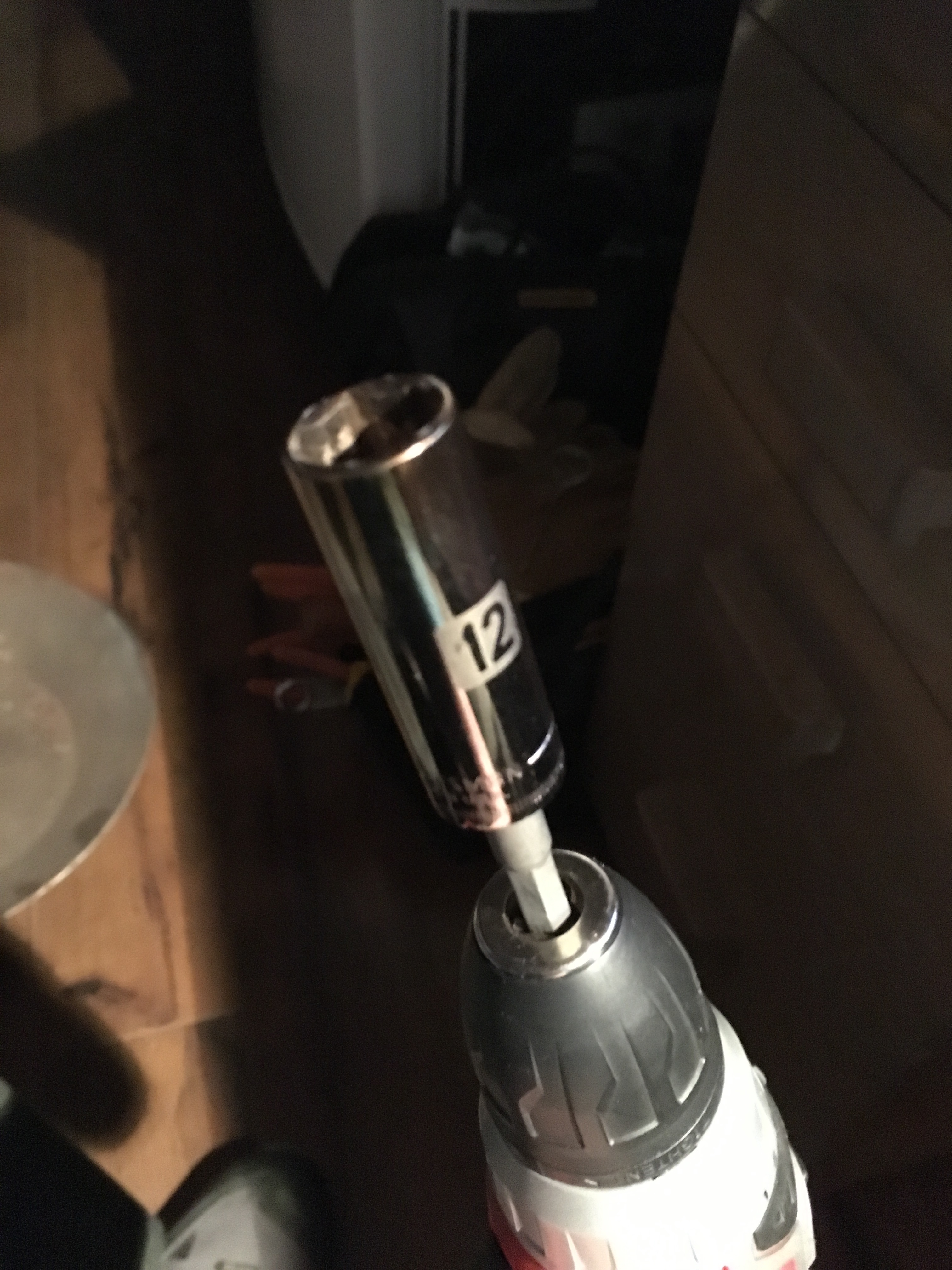
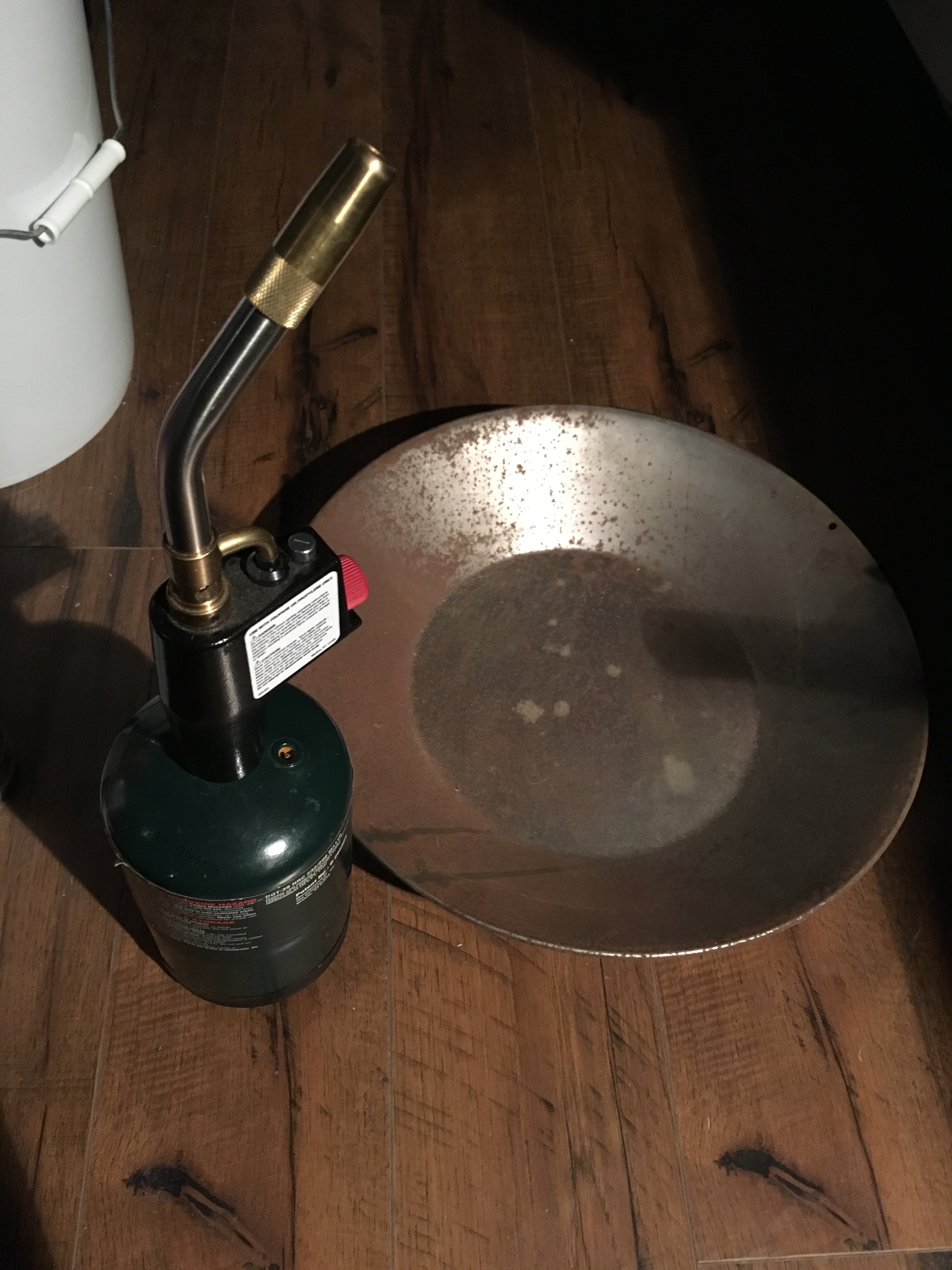
Here's
my cheap battery powered screwdriver with a deep 12mm socket and
my
propane torch with gold pan used to catch hot brass.
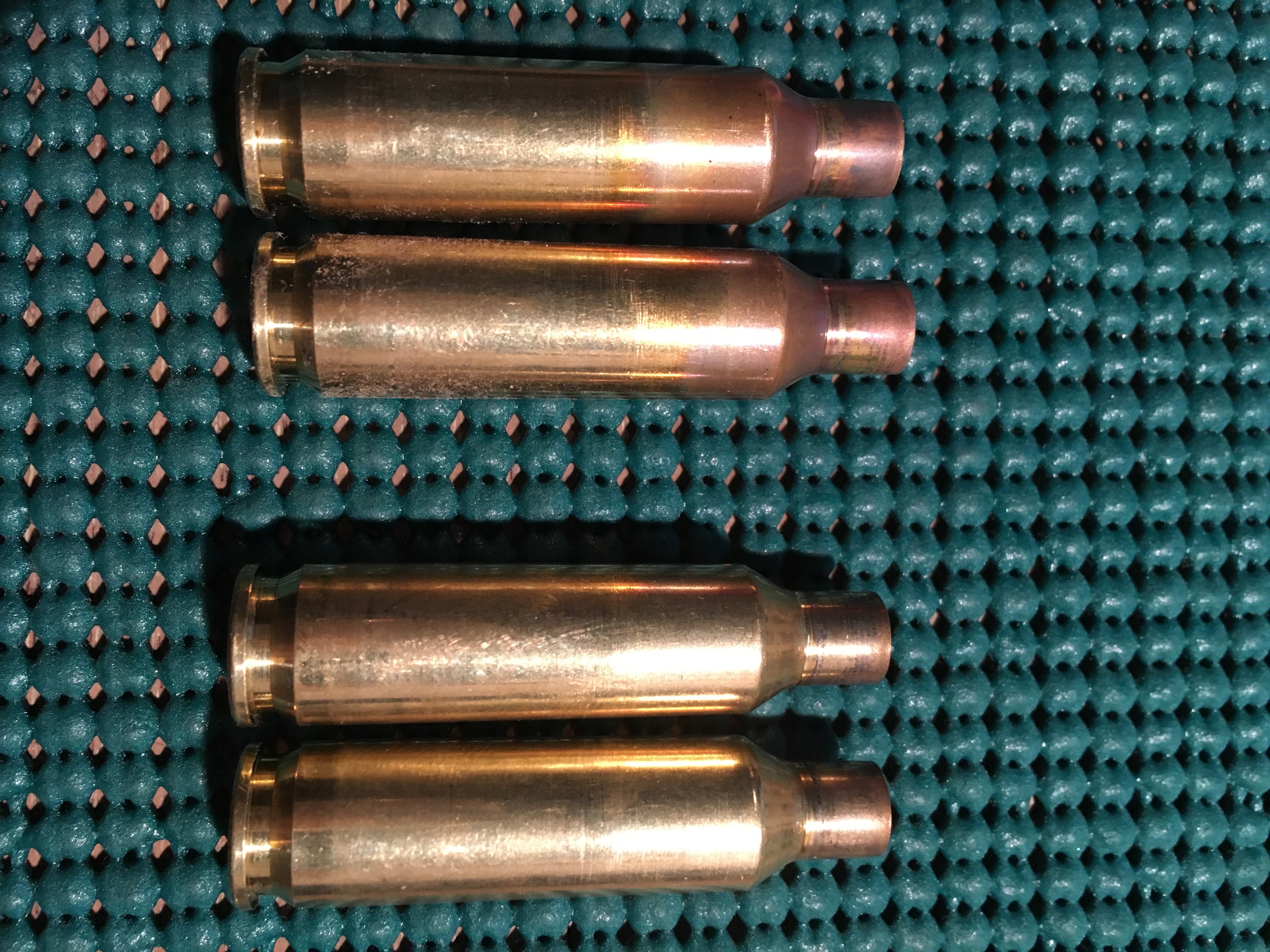
The
bottom two cases were annealed then fired. The top two cases were
annealed, fired and then annealed. Note the copper patina that is
typical on recently annealed cases, it fades over time. It is next
to
impossible to identify correctly annealed cases visually.
Since
this was written, I've moved to an Annealeez machine. The socket
and
torch method was too often getting a little red radiation off the
neck, which is way over annealed. Using 400 and 750 Tempilaq to
indicate temperature achieved, I calibrate the dwell time (time
the
neck is in the torch) for each run, or any time I move the torch
etc.
This ensures the cases a properly annealed, and most importantly
that
the body is NOT annealed.
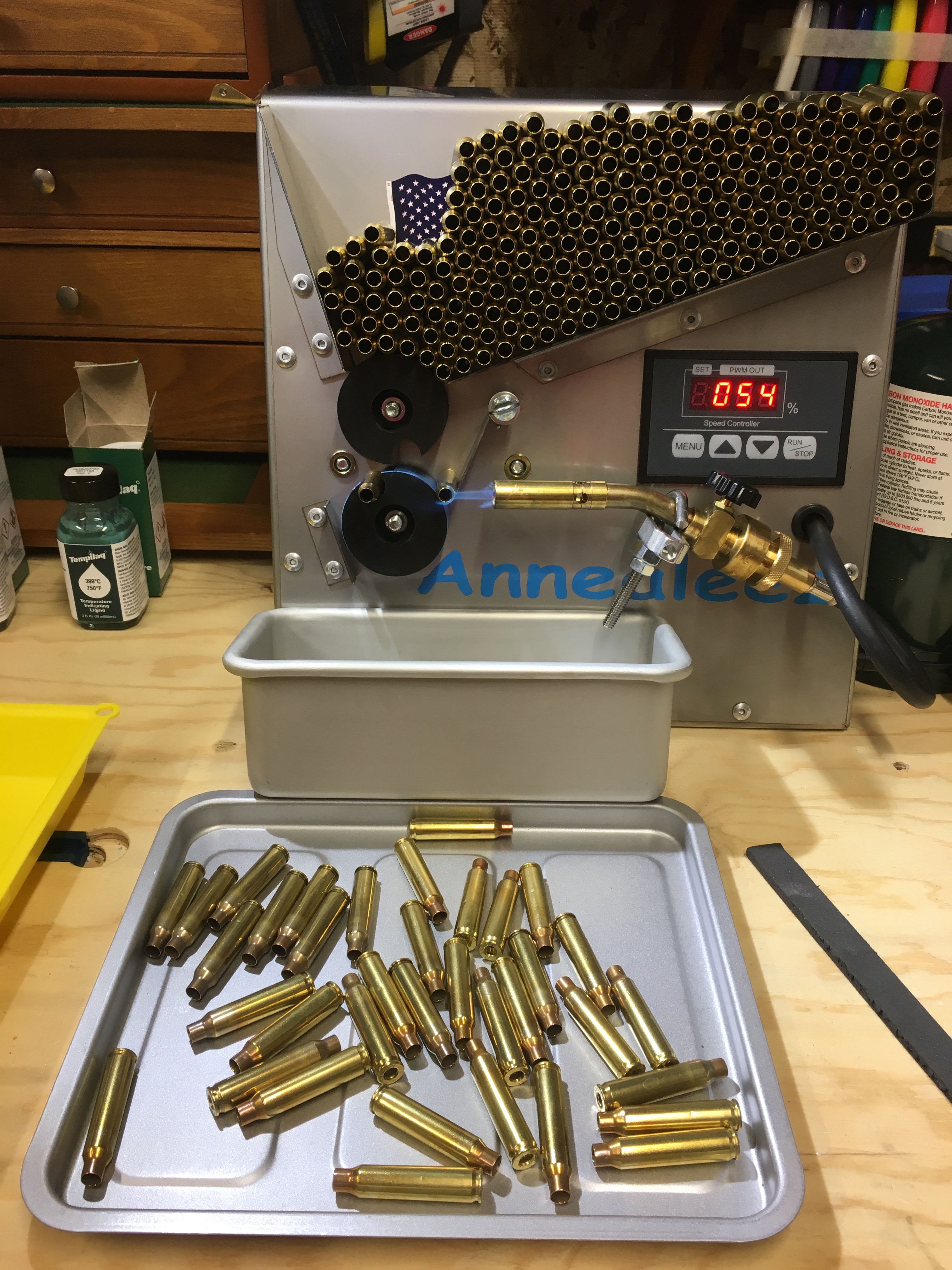
Also worthy of note, I don't clean my precision rifle cases
between firings other than to clean out the primer pockets (don't
want hot gunk spaying into powder and changing initial
conditions).
You can anneal cases before or after you resize them, but you
should resize them after you anneal them.
You can make your neck
turning easier if you anneal the neck before turning it.
My
routine reload is performed using Wilson hand dies and an arbor
press. All of my brass has undergone fire forming, trimming,
chamfering, flash hole deburing, and primer pocket uniforming
before
I put it in service. I have not found it necessary to clean or
tumble
the brass between reloads. I have found it easiest to run fired
brass
through the annealing process every time I reload it, as the first
step before neck sizing/decapping. At this point I am getting 20+
reloads on 204 brass, annealed ever 4th or 5th reload. I used to
only
get about 5 reloads on these cases before the necks became hard
and
cracked. I expect to get nearly infinite reloads now that I anneal
every reload.
An interesting effect of the way I reload,
keeping cases organized by rifle, fully prepared, fire formed and
neck sized is that the case length does not grow, the should
dimension remains consistent, cases chamber easily, and accuracy
is
outstanding. It may also have a lot to do with not running the
charge
above SAAMI PMax too.
For 'bulk' cases – such as 5.56 NATO, which I am using in increasing numbers to shoot the local ground squirrels in spring … but that's another story (see the “Accurate MSR” saga on the opening page), because it's a semi-automatic and 2 out of 3 of them are direct impingement (the gas makes it all the bay back to the action) which creates very dirty brass, I have established a 'cleaning policy' in conjunction with using a Dillon 650 XL progressive it works like this:
Fired cases are captured by a nifty gadget marketed by Caldwell that puts a net right up agains the ejection port. Since I ALWAYS use an adjustable gas block, I can dial down the bolt speed until cases are no longer getting dinged on the forward assist protrusion. Fired cases are collected (sometimes sorted by headstamp if I'm doing testing). When I've got 'enough', I deprime the cases using a Frankford Arsenal Universal Decapper. Next I wash them in my Lyman tumbler with Souther Shine stainless steel chips, enough water to cover the cases, and enough Frankford Arsenal cleaning solution to make a 40:1 dilution (good for 3-4 loads in the tumbler, easily 1,000 fired cases). I have hard water, so I rinse the cases and the chips mercylessly and ensure there are no chips hiding in the cases. While the cases are still wet I spread the cases out evenly in my Frankford Arsenal case dryer and dry at 120F until completely dry. I usually do this outdoors to make use of the lower humidity and light wind to aid the drying. What comes out is bright shiny, dry cases that are then stored for a while. When I'm ready to do another batch project, I'll pull those dry cases and run them over the Frankford Arsenal case trimmer. I know that when I full length resize the case it's going to grow 0.005” (5.56 NATO), so I have the trimmer set to 1.745” to get a finish length of 1.750”. The cases are deburred and chamfered using a VLD tool (on the trimmer), and then the primer pockets are cut with a tool that looks a lot like the RCBS Trim Mate Primer Pocket Uniformer pictured here. I'm not certain, but it looks like this particular tool has been discontinued.
Once
the cases have been 'Fully Prepped' they are once again stored
until
needed.
When I'm ready to load, I get a stainless steel 'steam table' tray and cover the bottom with cases, then mist Hornady One Shot, shake and roll the cases watching to see the lube coat the case bodies from contact with the tray. This typically takes two light mistings for 50 cases. I let the cases 'flash off' to get rid of the solvent, then they go into the case hopper and I'm ready to load. I try not to lube more cases than I will use immediately. Leaving the lube on the case for a day or two won't hurt anything, but much more than that and the cases get gummy and resizing suffers for it.
Speaking of resizing, as you undoubltely aware, if you've made it this far, you know I prefer to literally load by hand, using Wilson Hand Dies and an arbor press. Back in the 80' I was heavily into Metalic Shilouette shooting enough to keep a Hornady “Projector” progressive press busy every night I wasn't at the range. Those 357 and 44 Magnum loads, in my Contenders and Desert Eagles were 'rifle accurate' and I often just for the hell of it, shot those pistols against rilfes on the full scale range (rams at 500 yds) and won more than you might imagine! Those were the days! With the ground squirrels, I am shooting so many that the 17 HMR is getting far more use than the 204 Ruger. I want a bit more range and velocity than the 17 HMR and I want it in a semi-automatic platform – eg MSR (Modern Sporting Rifle). So that explains what I'm doing with the research into how to build an accurate MSR and load for it on a progressive. Some of the key takeaways I can give you at this point involve selection of dies. I don't want to overwork the cartridge brass so I chose a Redding Full Length Bushing Size die. I chose a bushing size of 0.245 because my Lake City cases are averaging 0.012 neck wall thickness, so that should resize the case neck to an ID of (0.245 – (2*0.012)) = 0.221 or 0.003 neck tension. Then I selected a 0.222 carbide neck sizing button that as the case is extraced from the die resizes from the inside out to a neck tension of 0.002. You can just barely feel the button pulling out. Since this is a carbide button it does not require lube, and because it is only making a very small change that's ok. So the big advantage? Two actually. I get to only lube the outside of the case, so powder does not stick to the inside, and I get a very concentric case neck with just the right neck tension. I also got a Redding Competition Seater die that has a sliding sleeve with extremely tight tolerences to help seat the bullet concentric. And if you've been keeping up, since I 'only' have 0.002” neck tension, I put a Lee Factory Crimp die (collet style) in the last position, and set it to just kiss the neck.
With these procedures and techniques I am loading very accurate varmint ammo as fast as I can pull the handle. Side Note: I don't pull the handle fast, I pulll it consistent and all the way both ways feeling everything … but even plodding along like that, the Dillon churns out match grade or better ammo at 3-4 per minute. Lots faster than I shoot squirrels (most of the time).
The Difference Between Virgin
Cartridge Cases and Fire-formed Cartridge Cases
A while back I
took 10 brand new Hornady 308 Winchester cases and did as little
to
them as possible, just full length resize, prime and then measure
as
follows:
VIRGIN CASES: (ES: is Extreme Spread)
Average
Case Length: 2.007" ES: 0.0045"
Average Weight Dry:
174.0 grains ES: 2.3 grains
Average Weight Filled with Water:
228.9 ES: 1.9 grains
Average Water Capacity: 54.9 grains ES: 0.5
grains
Average Neck Wall Thickness Min: 0.0135" ES:
0.0014"
Average Neck Wall Thickness Max: 0.0140" ES:
0.0006"
So then I dried the cases for a couple of days (a
previous test indicated that water wetting a primer doesn't kill
it).
Neck sized the case in a Wilson hand die, primed them with the
same
CCI LR primers used previously, and loaded them with a load I
normally use that shoots into about 3/8 MOA. I fired them in my
308
match chambered rifle with normal performance results. Keeping
them
in the order they were measured previously, I then ran the same
measurements on the fired cases and obtained these results:
FIRED
CASES: (Nothing done to case after firing, these cases should be
very
close to maximum chamber volume for this brand of case.)
Average
Case Length: 2.0087" ES: 0.0125"
Average Weight Dry:
173.3 grains ES: 2.3 grains
Average Weight Filled with Water:
229.5 grains ES: 1.0 grain
Average Water Capacity: 56.2 grains ES:
0.7 grains
Average Neck Wall Thickness Min: 0.0135" ES:
0.0007"
Average Neck Wall Thickness Max: 0.0142" ES:
0.0009"
The thing I was looking for was the change in
case capacity, but these numbers reveal some other information
about
what happens when virgin cases are fired the first time. You can
see
the case stretches slightly, the neck thickness is not
dramatically
effected, and the case capacity increases by a significant 1.1
grains
of water.
To show an example of what this means in terms of
performance; Quick Load says the virgin case generates 60,156 psi
and
achieve 2713 fps, while the fired case generates 57,011 psi and
achieves 2688 fps.
That's a muzzle velocity difference of 25
fps between virgin and fired cases in this example. There is a 25
nS
difference in muzzle time if you are interested.
One would
assume the same effect is present in all other cartridges to
varying
degrees, and would probably be directly proportional to the case
capacity.
Caliper Accessories
Bore or Case Datum Stops
Case Head Anvil
Modification: My Remington 700 firing pin has a little space around it, so primers crater into that space with any load. When measuring the CBTD I was having a problem getting an accurate measurement because of the primer crater, and I wanted the measurement before the case was sized or decapped. To allow the caliper to measure from the case head, I selected a washer, drilled the center out to a diameter a bit greater than a large rifle primer, and flattened it on a diamond stone. I then used double sided carpet tape to adhere it to the center of the Hornady LNL Tool's anvil. Now all primer craters go into the center of the washer and the case is measured off the rim of the case. You can see the washer in the last photo of the LNL tool below.
Vertical Stand
Tubing Micrometer - best (only) way to measure case neck thickness.
Vernier
Digital
Tubing Micrometer Accessories
Anvils
Stand
Gauge Sets
RCBS Precision Mic
Hornady LNL OAL Gauge
The Hornady LNL OAL Gauge is a serviceable tool for determining bullet seating depth, and CBTD (Case Base To Datum) dimension for setting full length sizer dies to the correct amount of 'shoulder bump' or 'setting the shoulder back'.
The tool comes in two types. The straight tool (for bolt actions) will work in gas guns (AR platform) but will not work in Garand or similar style actions. The curved tool (for semi-automatic actions) will work in bolt guns and all semi-automatic actions. The straight tool is very awkward in AR platforms.
There are a couple of things to know and understand using the Hornady LNL OAL Gauge to achieve accurate readings, and to avoid destroying the tools accuracy.
There is a right
and wrong way to install the tool onto your calipers. Look at the
picture below. The tool is correctly installed on the jaws of the
micrometer ,so that the centerline of the jaws is on the
centerline
of the tool. If you place the setscrew in the opposite hole, your
jaws will be offset from the centerline.
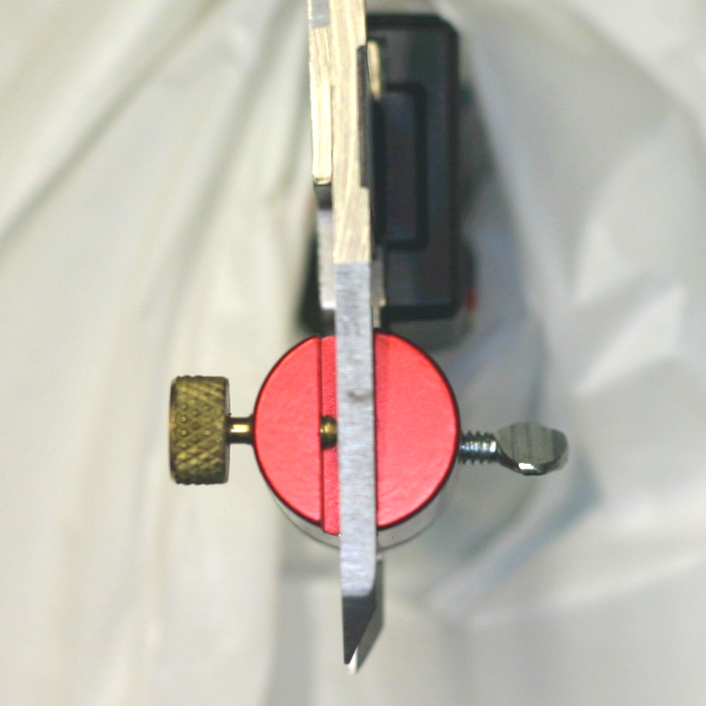
There is a flat section on the
plastic
bullet pusher piece that should be adjusted as shown. When it is
in
this position, the 'V' in the 'handle' portion will align under
the
set screw used to lock the adjustment of the bullet pusher. NOTE:
Be
VERY GENTLE with the setscrew because it can and will dimple the
pusher, and that will affect your ability to obtain consistent
readings. The setscrew should only be tight enough to transfer the
reading to your calipers and NO MORE.
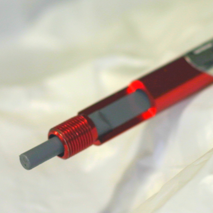
Install
the LNL Modified case by screwing it down onto the tool until the
base of the case is stopped by the outside diameter of the tool
body.
NOTE: Be careful to not overtighten the case.
Install the test
bullet into the mouth of the case, and adjust the pusher to hold
the
bullet in a 'reasonable' seating depth.
NOTE: When you place the
tool into the chamber feel for the case to fully seat into the
chamber with zero pressure on the bullet. The case shoulder should
be
the place where the case touches the chamber. On occasion the case
neck may hang up and produce a false reading.
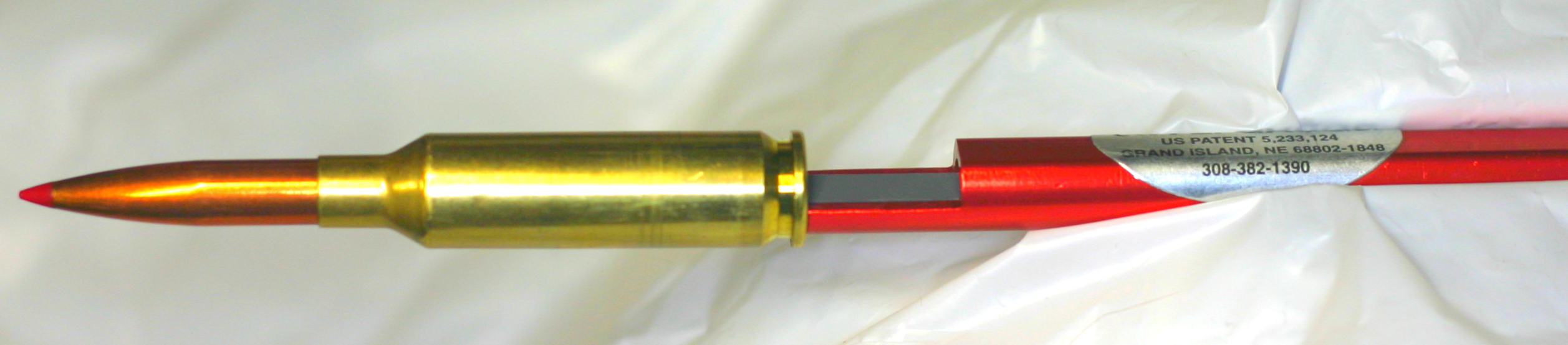
Once
the tool is inserted correctly into the chamber, hold the tool
body
to keep the case firm in position. Unlock the 'bullet pusher', and
GENTLY push the bullet until it stops.
NOTE: Often the bullet
will seat slightly differently in repetative tests. To prevent
this,
I put a very light coating of Imperial Die Wax on the bullet in
the
area where the bullet and chamber will meet. This also aids in
removal of the bullet when it gets stuck. A clean chamber and a
lightly lubricated bullet won't stick as often as a dirty chamber
and
dry bullet.
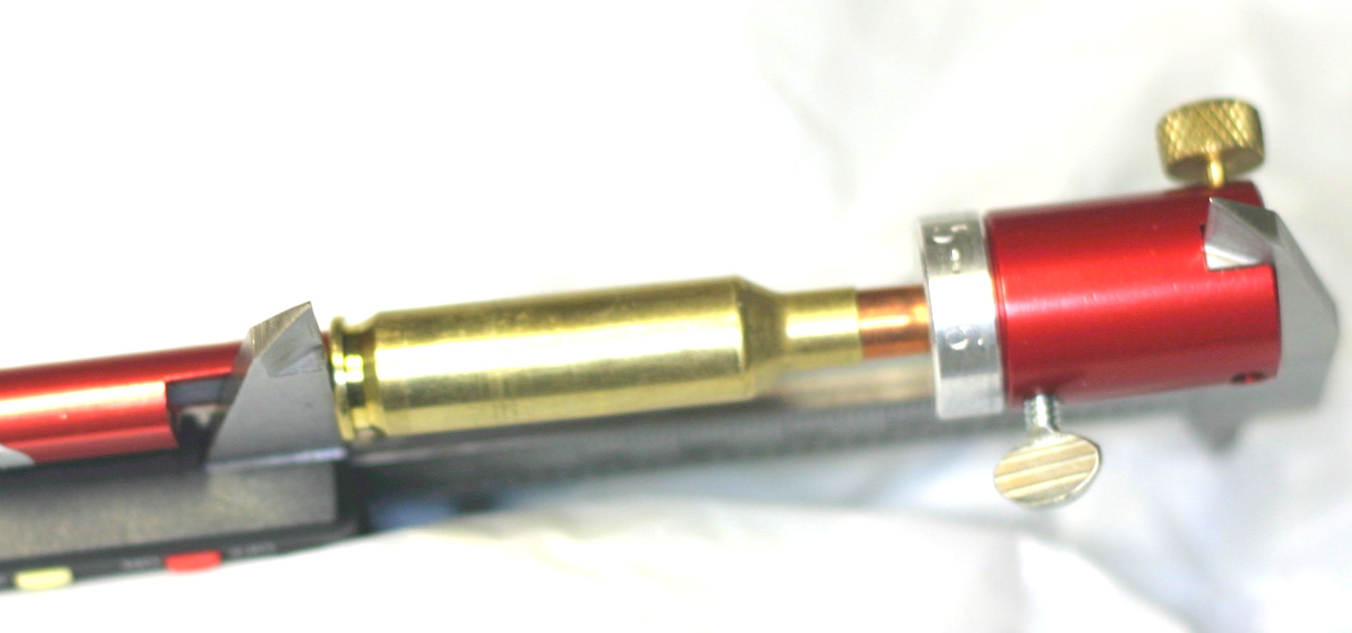
In
the picture above, note the lower blade of the caliper is
cenetered
on the centerline of the case. I have added a thumbscrew to the
LNL
tool top to allow changing the insert without needing an allen
wrench. HORNADY -- If you are listening, we need to be able to buy
these nifty knurlled thumbscrews!
Again, do not put any more force
on the caliper jaws than necessary to obtain a consistent reading.
Using excessive force will collapse the 'pusher' and may mark the
location where the setscrew locked its position, leading to
inaccurate readings in the future.
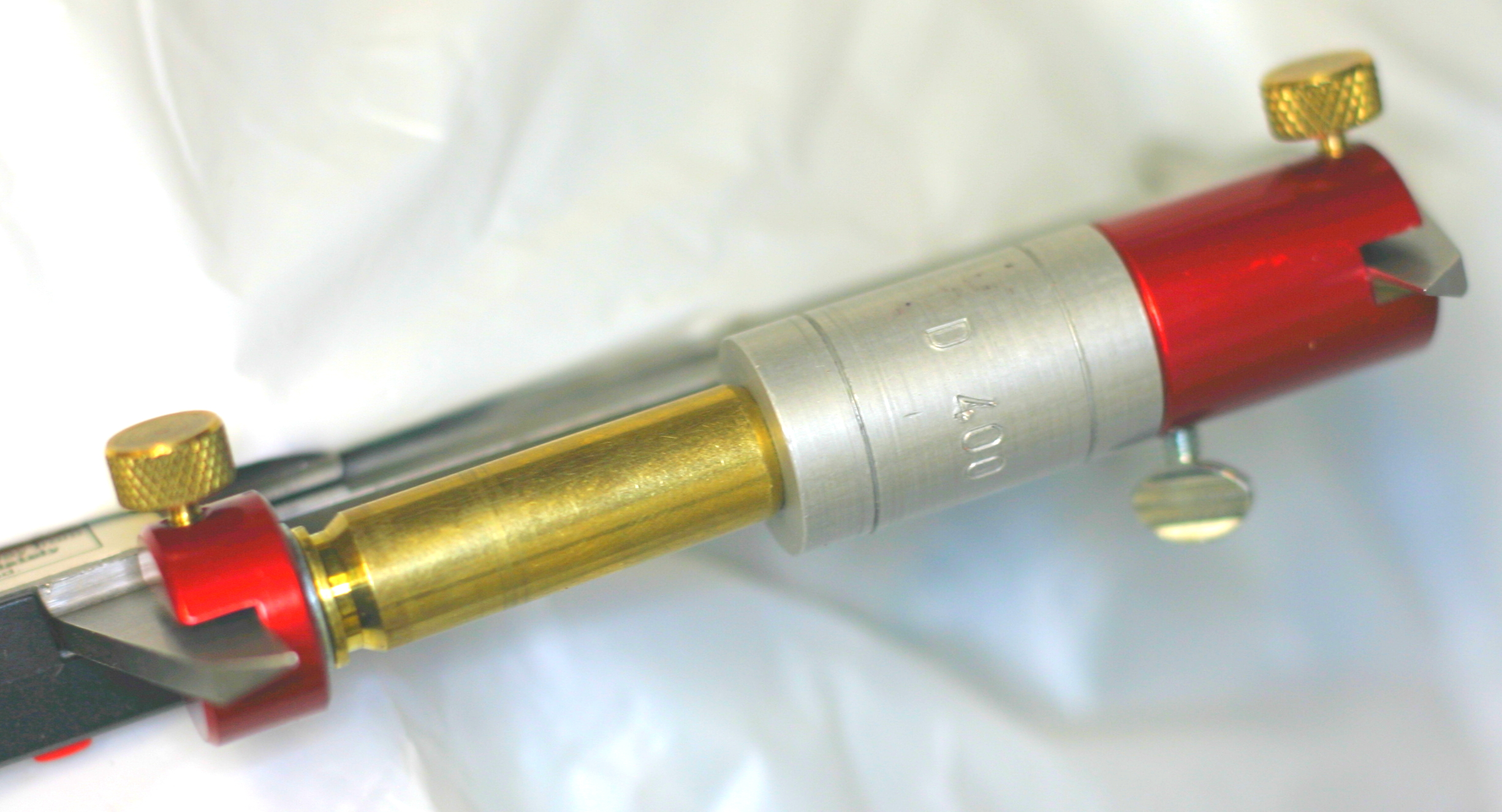
Swapping
out the bullet adapter for the case adapter allow the measurement
of
the distance from the base of a fired case, to the datum point on
the
shoulder of the case. The datum point is a measurement established
by
SAAMI when the cartridge is accepted by them. In general the
dataum
is the point half way up the shoulder of a bottle neck rifle case.
This point is the reference for the very misunderstood measurement
'Head Space'.
SAAMI drawings for rifle cases, note the
headspace dimension as the distance in the chamber from the bolt
face
to the datum point on the shoulder with an 'X' inside a circle.
The
6.5 Creedmoor chamber drawing is below.
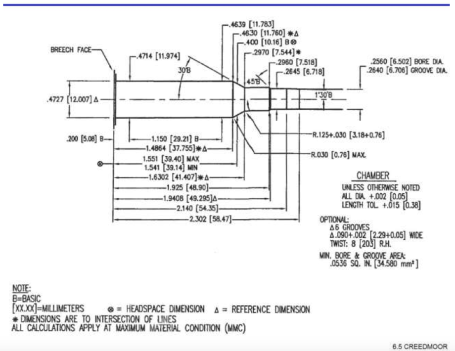
Ammunition
manufactureres (including reloaders) must keep the case base to
datum
(CBTD) measurement within the tolerance established by SAAMI or
risk
malfunction.
SAAMI performs exhaustive testing on each
cartridge it accepts for standardization and provides the range of
allowable CBTD on the drawing for that chamber.
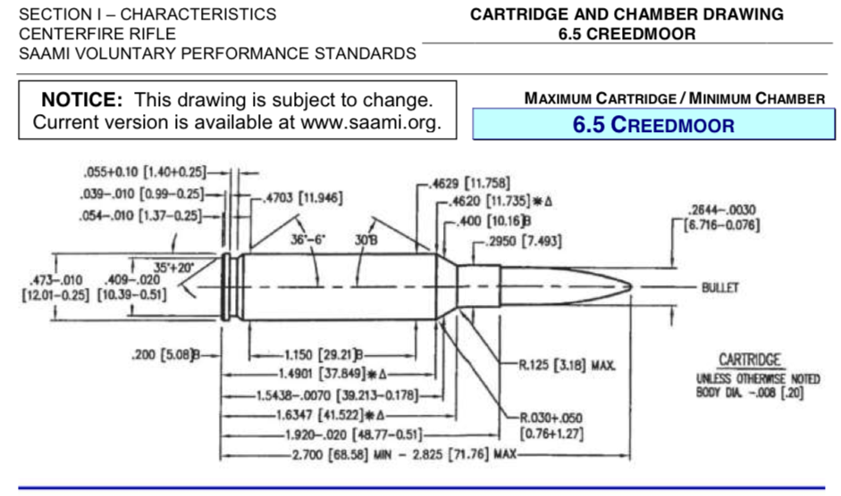
The
case CBTD may measure from 1.5368" min to 1.5438" max.
The
chamber may measure from 1.541" min to 1.551" max.
NOTE:
In this case, a maximum length case could be up to 0.0038"
longer than the chamber, and a minimum length case could be up to
0.0142" shorter than a minimum lenght chamber. Both extremes are
very undesirable, but should not create a dangerous situation.
When
a round is fired, its case expands to completely fill the chamber
in
all directions. As the case cools it typically shrinks 0.002" in
length measured from base to datum. Many reloaders use the
abreviation CBTD to note Case Base To Datum measurement. The LNL
tool
allows you to measure the CBTD of your fired case(s). Adding
0.002"
to this measurement will allow you to compare your chamber to the
SAAMI drawing for your cartidge. As a general rule of thumb, cases
measuring 0.010" less than your chamber's headspace should be
avoided, as they are likely to rupture, or at the very least will
begin thinning in the web area of the case, which after reloading
can
lead to case head separation, and that leaves the case body stuck
in
the chamber.
SAAMI rifle drawings
are available from them here.
A
useful modification I made to my LNL tool was to drill out and
flatten a washer then using double sided tape I stuck it on the
anvil
so that it was centered on the case body. This allows fired cases
with raised firing pin impressions on the primer to be measured
directly, without the necessity of removing the spent primer (and
maybe changing a dimension on the fired case)
Bryan Litz of Applied Ballistics has made both a video and a document covering the Tall Target Test. You should start by reviewing both.
When you mount a tactical scope on a precision rifle, you expect to be able to make sighting corrections that accurately place your rounds on target at long range. Here are the steps to ensure you have correctly performed the work:
Select a mount - precision rifles typically use MIL-STD-1913 or 'Picatinny' rail. Such rails come in various configurations providing from zero (0) to at least 30 MOA (Minutes of Angle) slope to enable scope adjustment for long distance shooting. Typically 20 MOA is sufficient for most sporting calibers, while 30 MOA is typically reserved for large calibers and extreme long range.
Select a scope - tactical scopes have easily adjusted elevation and windage knobs, and probably will have a parallax adjustment. 1 inch (25mm) scopes have less vertical adjustment range than 30mm or 35mm tube scope.
Select a level that mounts to your scope body. Levels that attach to your rifle only tell you the rifle is level, and are not appropriate for precision rifles because they can not be ajusted to match the scope reticle.
Know your scope's tube diameter (in millimeters).
Know your scope's objective (toward the target = objective) diameter.
If you have an adjustable cheek piece placing your eye directly behind the scope when you are in your natural point of aim is much easier. If not, you need to find the height of rings that will place the scope in the correct relationship with your eye.
You want to select rings that hold the scope close the lowest position that allows a scope cap on the objective with a little clearance. This position must allow you to get your eye directly behind the scope in both prone (bench) or standing positions.
Sometimes the best way to find the correct ring height is to take your scope and rifle to where you are going to buy rings and try different heights.
When you select rings, calculate your scope centerline to bore centerline height to be used in your firing solution. Many actions have a gas relief port on the side opposite the bolt knob, about in line with the base of a chambered case. Typically this hole is in line with the centerline of the barrel. Measure from the center of that hole, to the center of the scope tube. Accuracy to 1/4" is usually sufficient for solutions to 1,000 yards.
Check your base or rail to ensure it is firmly installed. If necessary remove it, clean the area, re-install with Locktite blue. Refer to manufactures documents for correct torque.
Place the scope close to your rail, and estimate where it will end up. Estimate the correct location for each ring. Mark the location (many rails have numbers for this) where the rings should be mounted.
Locate your ring base positions on the rail so that the scope is supported on either side of the adjustment housing, and so that there is maximum room to adjust the scope forward and backward.
Place the ring base onto the rail. If you have a choice, place the ring so the clamping screw is on the side away from the ejection port (left side for a right handed rifle).
Loosely install the ring, and then firmly press it toward the butt of the rifle, while screwing down the clamp. Keep the base of the ring flat to the rail. Stop when the clamp is firm, well before final torque specs. Repeat for the other ring. What we are doing is taking out the ability of the ring to move under recoil, and ensuring the ring has full flat contact with the rail, while still allowing for the possibility of moving it as the installation progresses, without stress.
Place the scope into the lower ring halves.
Loosely install one or both ring tops so the scope can not fall, but can move forward and backward.
Test the rifle in prone or bench and standing positions. Move the scope forward and backward in each position until your eye is in the eyebox (area where the scope 'pops' open to full edge to edge view). Test the eyebox position at maximum scope magnification where the eyebox is smallest. Keep going back and forth until you have the best compromise for the two extreme positions of your head. Confirm that the adjustment remains correct at lowest magnification. If you know you will only shoot from one position, only adjust to that position (and then kick yourself when you decide to shoot in another position some time later!)
With the scope correctly positioned forward and backward, place a masking tape marker on the scope tube to indicate where the front edge of the rings are.
Establish a temporary working installation by rotating the scope until it appears to be vertical as you look through it. Tighten the rings, but not fully. They should be tight enough to withstand a few shots as we finalize the adjustments. If in doubt, go ahead and torque the tops down, and torque the mounts down.
Final adjustment will be performed as part of the Tall Target Test (next).
Review the Tall Target Test video and document
NOTE: The Tall Target Test can be performed while you are breaking in a new rifle barrel. Read Rifle Cleaning Protocol
Assemble a target with sufficient height to contain both the aiming point and a bullet fired with the maximum vertical elevation your scope can produce from the aiming point.
NOTE: Scope manufacturers list the total elevation adjustment, it is up to you to mount your scope in such a way as to maximize the use of that range. For long range shooting, typically a 20 MOA rail is used to tip the front of the scope down by 20 Minutes of Arc, moving your 100 yard zero to the lower 1/3 of the scope adjustment range, and maximizing the available upward adjustment. For example, the Vortex HS LR 6-24x50 FFP XLR moa scope has a total of 65 MOA vertical adjustment, and 40 MOA of total windage adjustment. From the factory, the scope is set at the mid point where there is about 32 MOA up and 32 MOA down, 20 MOA left, and 20 MOA right. When placed on a 20 MOA rail and zeroed (if all else is in alignment) there will then be about 52 MOA up, 12 MOA down, and still have 20 MOA each left and right.
If your scope has 30 MOA up adjustment you'll need a target about 36" tall, for the 52 MOA in the example above, a 4' target is too small, and going all the way to an 6' target is probably the easiest as 54.4" will be required if everything is working correctly, perhaps more if not.
Your target needs to have enough room below the bottom and above the top to capture any groups or shots that are misplaced, probably 6"-12" is sufficient.
Your tall target should be placed on a backer that has a true straight edge, and that edge should be dead vertical as measured by a long construction level. The line down the middle of the tall target should also be measured vertical.
Before you zero your rifle and complete your scope installation, you have one adjustment remaining, calibrating the elevation control to the fall of gravity.
Build a shooting position that is naturally comfortable for you, with lots of support for the rifle.
Find Your Natural Point of Aim.
Close your eyes, settle your position, open your eyes - you should remain on target. Adjust until you can do that.
Adjust the position of the butt of the rifle in the pocket of your shoulder until it is comfortable and repeatable.
Repeat the Natural Point of Aim drill.
If at this point your scope crosshairs are no longer vertical:
Using the long edge of the Tall Target, or the vertical line if its more visible, rotate the scope so its vertical cross hair is aligned to the measured vertical edge of the target.
Retest your Natural Point of Aim, and ensure the scope crosshairs now come up vertical every time and that the rifle feels natural, and the butt fits well into your shoulder pocket.
Complete the tightening of your scope rings to finish your scope installation.
Place your scope level where it is visible to you when you are in firing position. Often that is forward of the scope control housing, and may be on either side of the ring. It must be on the straight section of the scope tube, and not interfering with anything.
Adjust your scope level to indicate level when the crosshairs of your scope are in alignment with the long edge of the tall target, and finalize the level installation.
You will need a regular target to establish zero.
Zero your rifle so that the bullets hit where the crosshairs meet.
Zero your rifle at exactly 100 yards.
Place your tall target at exactly 100 yards.
Make sure the bottom of the target is far enough above the grass that you can easily see the aiming point.
Shoot a 3 shot group at the aiming point
Increase your elevation to the maximum you will use and shoot a 3 shot group while continuing to aim at the aiming point at the bottom of the target.
NOTE: If your group develops off the vertical line, you may
need to make a minor correction to the scope rotation and repeat
the
test. Do this before you continue, and be sure to adjust your
level
to the new rotation.
There are a couple of additional tests you can do while you have this setup in place.
Test your windage by dialing 5 MOA right and 5 MOA left shooting a group at each setting.
Return your windage to zero, and move your elevation down by 5 MOA (being careful not to overshoot, so the turret only turns in one direction), fire a shot, move down 5 MOA, fire a shot, repeat until your setting is 5 MOA above your 100 yard zero. Then dial up 5 MOA repeating the pattern from bottom to top, then repeat from top to bottom to end up with 3 shot groups every 5 MOA between zero + 5 MOA and max - 5 MOA. By doing it this way you will be able to tell if your vertical adjustment has 'slop' because these groups will be quite a bit larger than normal, and the 2nd shot will be out of the group. This is important to know, and can be mitigated by always arriving at your sight setting from the top or from the bottom to settle the threads on the elevation adjustment. If these groups are large and don't seem to have two shots together most of the time, it may be your scope's erector spring is erratic. Tapping the top of the elevation knob with a knuckle after each adjustment, has been known to cause this condition to rectify.
You can also determine if your elevation control is linear, does it move the same amount per click through its entire vertical range. Each intermediate group should be centered at 5 x 1.047" = 5.235" (call it 5-1/4") above the previous group.
Keep the record of your Tall Target Test in your DOPE book. Well documented pictures are useful too.
Beginning Development 01/12/2019 --
NRFP
For long range accuracy it is critical to
know the true range to your target. As the bullet travels away
from
the muzzle it slows down due to drag, by the time it is 500 yards
or
more down range it has begun to reach the zone where its vertical
motion (fall due to gravity) is beginning to affect its ability to
hit within 'x' inches of where it was pointed. From here on the
bullet only falls faster (32 feet for every second of travel times
every second of travel). So instead of a 'flat' trajectory, we
begin
to see an arc and as distance increases the angle of the arc
becomes
more vertical. In mathmatical lock step with the increasingly
vertical arc, we must know target distance to more and more
precise
value, or risk missing the target because of errors of just a few
yards.
LRF laser beams in the first generation equipment were
barely capable of ranging a cow at 500 yards. Their lasers were
not
very well colminated (parallel) and didn't have much power. In
addition they didn't always use the best frequency (color,
wavelength, etc.) to reflect off of the types of targets shooters
(both hunters and target shooters) were trying to range. Cabelas,
Nikon, and other consumer LRF's in the sub $500 range are
representative.
In the second generation of consumer LRF's the
beam colmination and power went up considerably. Ranging a
standing
cow at 1,000 yards was now run-of-the-mill. Gunwerks G2BR
(original)
and others costing over $1,500 are represnentative.
By 2018
several manufacturers were competing for the extreme long range
shooters dollars and thus constructed what I'll call the 3rd
generation of LRF's. These generally are capable of ranging a
standing cow at somewhere beyond a mile.
To achieve these
improvements the laser beam had to be more parallel, contain more
power and reflect better. The detector had to become more
sensitive
too.
Wikipedia: Laser
Rangefinder
Wikipedia: Beam
Parameter Product
Your new precision rifle comes from the factory after being fabricated and tested. Depending on the factory, and the order specifications for your rifle, it may have had the bore cleaned and a thick protective coating of Cosmoline, oil, or machine coolant . In any case, it is in the best interest of barrel life, that your first act upon receiving a new rifle (from any source) is to clean and inspect the barrel.
Initial cleaning to remove factory coatings may be accomplished by plugging the barrel at the muzzle end, placing the rifle muzzle down (on a drip pan), and spraying a lot of WD-40 into the chamber end. Leave the WD-40 to dissolve anything left over from machining in the barrel for 10 minutes, then drain and wipe out with a cleaning rod and patches.
One of the challenges of cleaning a rifle is to not get cleaning solvent into places it doesn't belong. One of the best methods I've found to do that is to purchase the appropriate 'Possum Hollow' bore guide and solvent port adapter. Once installed this bore guide keeps everything out of the chamber, and everywhere else that isn't the bore. You'll want to clean the chamber separately.
NOTE: Cleaning using long shoe string style tools is perhaps useful in some environments, and for some pursuits. In my opinion, it is not appropriate for precision rifle cleaning, and should never be used in precision barrels except as a last resort.
NOTE: Cleaning rods come in a wide range of styles. For precision barrels, steel rods are out because steel is hard enough to destroy the interior of the barrel. Brass is softer, yet it to can damage the barrel if misused repeatedly. This leaves us with coated rods and carbon rods. I prefer Gunslick Carbon rods and their brass rifle jags. I do not find any reason not to use J. Dewy rods, however read their disclaimers about corrosion and fitting. Both style rod come equipped with a ball bearing handle, which I prefer. J. Dewy has a line of jags and tips that do not react to the chemicals typically used to remove copper, so they don't produce a false positive reading, which you sometimes get from a brass jag.
NOTE: Cleaning patches from Montana Extreme seem to me to be the top of the line for use in precision rifle barrels, and there's nothing wrong with their cleaning rods as they are coated.
NOTE: Cleaning Solvents from KG Coatings are useful because they are specific for Copper or Carbon. Few of the mainstream manufacturers listed above have differentiated solvents. It is important to be able to remove only Carbon and leave Copper intact in the barrel. KG-1 Carbon remove does just that. It is difficult to remove Copper without damaging the barrel. KG-12 removes Copper without any chance of damage to the bore.
NOTE: Gun oil (KG-410) is a fine oil for protecting and lubricating as necessary however, I have found MILTECH-1 Weapons Lubricant lives up to its advertising, and is extremely useful as a bore conditioner.
Some folks believe the best accuracy can be obtained by cleaning everything out of a barrel as often as possible. This philosophy has won bench rest competitions, but is not practical for weapons used in the real world where many shots are fired between cleanings. Our challenge is to analyze what occurs inside the barrel with the first shot, and subsequent shots, and why accuracy falls off over time if the bore is not cleaned, and what to remove, and when.
As the bullet moves into the barrel, pressure rises to its maximum typically within the first 6 inches of travel. At this point the temperature has also reached maximum and there is still a lot of unburned powder being accelerated down the barrel. The bullet jacket has been forced into the rifling and the bullet is beginning to accelerate very quickly. The hell that exists inside the chamber and first few inches of the barrel is so intense that it will erode the machining, and leave the surface of the barrel checked and crazed. There is little that cleaning can do to alter this condition, nor prolong its useful lifetime.
As the bullet moves further along the barrel pressure and temperature of the gas drops quickly and significantly to the point it no longer poses a threat to the barrel material or machining. Bullet velocity has increased substantially, and now jacket material is melted and pressed into whatever irregularities exist, particularly onto the lands (raised surface of the rifling), and the corners of the bottom of the grooves, and machining marks along the bottom of the grooves.
As the bullet continues to accelerate in the last 1/3 of the barrel, it reaches its maximum velocity, and the frictional heating of the jacket is at maximum. This is the area most likely to see heavy copper plating.
When the bullet exits the barrel, the gas and residual debris are ejected at a speed much greater than the bullet, but some of the debris nearly always remains in the barrel. This material is mostly carbon.
When the next shot is fired, whatever carbon is left in the barrel is pounded into the barrel by the bullet, or is ejected ahead of the bullet. Given the very acute angle between the bullet ogive and the barrel, a lot of the carbon is trapped and pounded into the barrel walls. Some of the copper that is deposited by this shot will have a carbon layer under it, and some will find either bare steel, or previously deposited copper to adhere to.
When subsequent shots are fired, whatever material that can move is ejected ahead and behind the bullet, and the remaining material is again pounded into the walls of the barrel. Copper continues to adhere, mostly to locations where it has begun to plate the surface.
As the first shot is fired, a certain resistance to the bullets movement down the barrel occurs.
As the second and sometimes a few more shots are fired, each experiences a slight increase or decrease in resistance to movement as a function of the lubricity of the material previously deposited in the barrel, and the changes in that materials distribution.
At some point an equilibrium is established where each subsequent shot feels essentially the same degree of resistance to movement, and at that point muzzle velocity variation is reduced, and accuracy begins to occur.
This condition will persist typically until carbon buildup causes a loss of accuracy, which in my 6.5 Creedmoor H4350 load has been found to be at about 300 round intervals. In my 308 Winchester Varget load, the interval is closer to 400 rounds or more. In my 204 Ruger Varget load, the interval is about 100 rounds. In my SR556 CFE223 load the interval seems to be greater than 500 rounds. From this I conclude that the available surface area of the barrel and the carbon debris load of the powder are the controlling factors determining when accuracy is degraded and how often a carbon cleaning is required.
To restore accuracy when carbon fouling has degraded it, all that is required is to run a carbon specific cleaning cycle. I use a nylon brush of the appropriate size, soaked with a few drops of KG1 and quickly run the brush all the way down the barrel and out the muzzle, then back into the bore guide body for a count of 1. I repeat to a count of 25 as quickly as is practical (KG1 is designed to work best when agitated this way). Then I run a patch soaked with KG1 through and out the muzzle. This patch will be extremely dirty. I repeat the KG1 patch one more time, this patch is almost clean, so I repeat again and the 3rd patch usually comes out with no carbon at all. At this point I wet a patch with MILTECH1 and scrub the barrel in 4" sections from end to end to ensure the MILTECH1 is reaching into all available spaces. Next I make a point to fire the barrel 3 shots before I put it away to get the MILTECH1 up to operating temperature, and to season the barrel for the next cold bore shot. This is probably me being OCD, because typically those three shots all go into the same hole.
I am totally convinced that the MILTECH1 routine inside the barrel has stabilized the accretion of copper and distribution of carbon in such a way that it has made the barrel generate more uniform velocity. I'm also convinced the MILTECH1 is responsible for the extremely fast carbon cleaning cycle.
Carbon cleaning cycles are so quick and easy I carry the required material in the gun case, and can do one of these anywhere, anytime in just a few minutes.
At some point in the future, a carbon cleaning cycle will not restore accuracy to the customary 0.25 MOA, and I will decide it is time to do a copper cleaning cycle, which goes like this;
First do a carbon cycle but omit the MILTECH1 finish.
Perform the same nylon brush treatment using KG12 and 25 strokes followed by KG12 soaked patches. Watch the patches for blue streaks which are dissolved copper. Repeat the KG12 brush routine followed by the KG12 patches until no streaks are present. Follow the KG12 routine with a degreasing using brake cleaner soaked patches and/or rinsing the bore with brake cleaner. After degreasing, MILTECH1 the bore, and wipe KG4 Gun Oil liberally on all other surfaces. KG4 can be left on for storage. Put a note on the rifle to MILTECH1 again, and perform a break-in cycle before next use.
Copper cleaning cycles generally involve more material than I carry with the rifle, and typically are not as critical to be able to perform in the field, so they are accomplished back in the shop at home.
Clean the bore. Clean it to bare metal using the Copper cycle with degreasing and finish with MILTECH1.
Fire one round
Perform a copper cleaning cycle including the MILTECH1. Repeat five (5) times.
The idea is to allow copper to steel contact so as to increase copper deposition quickly.
Fire 5 rounds
Perform a copper cleaning cycle including the MILTECH1. Repeat five (5) times.
NOTE: The idea is to achieve muzzle velocity variation stability. If you know the typical ES (extreme muzzle velocity spread) for 5 shots from this barrel when seasoned, and you see that the ES is at that level after just a few shots into the 5 at a time part of the protocol, I recommend you consider the break-in complete and move on. If on the other hand, ES is still high, continue with the 5 shot portion of the protocol until ES drops to previously recorded low number or below. This comment is also valid for initial break-in, however since you have no data on previous ES with this barrel, you can only be guided by raw numbers.
Using my 6.5 Creedmoor 143 ELDx 2652 fps load, changing the MV and looking at the come up predicted by Applied Ballistics Mobile we find the following:
MV +25 fps to 2677: U29.55 MOA
MV +0 fps to 2652: U30.15 MOA
MV -25 fps to 2627: U30.80 MOA
So in this load, a variation of +/- 25 fps results in an impact variation of 1.25 MOA
If we distribute 10 shots evenly over the 50 fps variation the SD would be: 16.02
Were we to have 5 shots at each velocity, even though the ES remains 50, the SD becomes: 26.35
If we change the number of shots to 5, and set the ES at 25, with an even distribution of velocities the SD becomes 10.1
In summary, when performing a break-in cycle, once you are into the 5 shot and repeat loop, if you see your ES for 5 shots at or near 25 fps you can probably stop the break-in cycle with no adverse effect.
Here is where I will post articles describing things I've purchased, modified, or engineered from scratch to use in pursuit of accurate long range shooting, precision reloading, or any related topic.
Eric and I have been building and testing shooting benches for a while now, and I think my latest design is pretty close to the ‘perfect’ portable shooting bench.
So what does ‘perfect’ mean in this context?
1. Light enough to move any component easily with one hand at full extension.
2. Minimum number of components.
3. Sturdy and stable enough to realize about 95% of the accuracy of your rifle.
4. Comfortable enough to spend all day shooting.
5. Large enough to support load development (clipboards, chronograph, portable computer, ammo, small stuff.)
To build this bench you’ll need to be able to cut pipe fittings at accurate angles and cut 1/4” flat steel bar at 90°. Both of these operations can be performed using a cheap chop saw which you should buy used at a pawn shop because when you get done cutting metal (with a cut-off wheel) the saw won’t be any good for anything else.
In a quick Google search I found a used Delta 10” Miter Saw (SM100M) for $39.99. In the same search I found cut-off wheels for metal cutting in the range of $5-$10.
SHOPPING LIST -
Total Bench & Legs: $155.56.
Total with Gibralter stool: $230.51
1-1/8 x 23-1/4 x 48 Edge Glued Board Homedepot $25.55
Cold rolled steel flat bar 1/4”x4”x24” ($16.17 on eBay ships for $16.33) You may find this locally for less.
1” NPT coupling 3 each, select the longest available, (makes 6 attachments) Homedepot $2.95/ea.
Legs 1” x 36” pipe 3 ea. Homedepot $13.65/ea.
Feet 1” NPT pipe caps 3 ea. Homedepot $2.49/ea.
Helmsman Spar Urethane 1 qt. Homedepot $16.57 or 11.5 oz spray $9.56\
Two coats of Spar Varnish initially, repair coats annually. Obtain a can of cleaning duster like for your computer - use it to displace air [oxygen] before re-sealing the urethane, it will not skim, and will be ‘factory fresh’ to the bottom of the can if you do this every time. Make sure you have mineral spirits available for thinning and cleanup. I use heavy duty Nitrile gloves for reloading (keeps hands clean, better grip and no oil transfer), if you’ve got ‘em use ‘em while varnishing too.
CONSTRUCTION
Screw the coupling onto one of the
legs, just enough to hold it firmly. Set the chop saw with the
cutoff
wheel installed to cut 14°. Cut the coupling into two even halves.
Use the leg to control the work, watch out for sharp edges and hot
material! Do this until you have 3 ea. couplings with sufficient
thread to hold the legs firmly. (I think maybe an angle of 7°
would
work a little better but I haven’t tried it yet.)
Reset the
chop saw to 90°. Accurately measure the flat steel bar width, and
cross cut it to be square.
Using a drill press if you have
one, or a hand drill if you must, drill a 9/32” a hole centered
3/4” in from each edge, at each corner. Chamfer all cut edges on
all pieces.
Set the couplings onto the 4x4 attachment plate.
Place two of the cut couplings at 45° and one at 90° (45° points
to a corner, 90° to the middle). Weld the couplings in
place.
Prepare the bench top by cutting out the area to sit
in, I made mine for a right handed shooter by cutting out an area
roughly 12” long x 9-1/2 wide on the left back corner. I found
that
clipping the outside corner a little and sculpting the line eased
a
‘poking’ problem when I was up tight on the rifle. Make sure you
leave room for the leg attachment to be on the centerline, and all
the way back to the edge. Cut all sharp corners at 45° (say about
1”
back from the corner).
Sand both sides of the bench to 220
grit.
Using a 45° chamfering bit in your router ease all of
the edges on both sides.
Turn the table top upside down, place
the forward leg mounts so the couplings point forward and outward.
Move the plates until they are 2” in from each adjacent edge, then
drill a very small (1/16”) hole in the exact center of each hole
in
the plate.
Flip the top over to right side up. Use a 3/4’
Fortsner Bit to create a 1/2” deep pocket for the bolt head.
Center
the Fortsner on the 1/16” hole.
Flip the top over to the
underside. Replace the leg attachments. Drill a 9/32” hole all the
way through at each attachment point.
Touch up by sanding to
220 again. Tack off with a cloth dampened in mineral spirits.
Following the direction on the can of spar varnish apply one coat
on
each side.
Sand to 220 grit to level the spar varnish, and
apply a second coat. If you are working in the shade at 60℉ this
coat should be able to be brushed on as a flood coat if you work
quickly. Watch for runs and clean them up as best you can. If you
thin the Urethane slightly with mineral spirits you can get the
2nd
and subsequent coats to come out like glass. Be sure to get
varnish
into all of the holes (natural and man made).
Install the leg
holders with 4 ea.: 1/4 x 20 - 1-1/2” carriage bolt, 1/4” washer,
and 1/4-20 self locking nut (nylock). Because the laminated pine
top
is rather soft, the carriage bolt may try to spin as you tighten
down
the nylock. You can reduce the tension of a nylock by running a
tap
from the bottom of the nut until some of the nylon has been cut
away.
Test until you find how much you need to cut, then do all the
nuts.
Alternatively use regular nuts and a thread locking compound. Be
careful not to over tighten the nuts.
Find the center of
gravity (test balance side-to-side, then front to back, mark the
intersection), and install a handle on the bottom centered on this
point. I put mine at 45°, and so far it seems to be working. You
might want to put one pointing each way, or you might want to use
a
round knob type handle.
You may want to run a wire brush up
and down the legs then paint them with a metal paint, and install
the
caps with more force than you can apply by hand (and/or use a
thread
locker here too). Those caps may be all that gives you the
necessary
torque to remove a leg in the field. (if your legs tend to stick,
you
can drill a hole sized for a screwdriver or something … that will
also help you tighten them down, but I haven’t found it necessary
on my bench yet.)
For extra credit you can setup two of the legs with slip-fittings and coordinated through holes to accept a clevis pin. This will allow you to adjust the bench for up/down and left/right to accommodate shooting in a hilly environment. Imbed a circular level in the top to aid in setup. Alternatively just take a small shovel along to change the level of dirt under the leg(s). (I’ve always got a small pick and a small shovel on the UTV for sanitary and brush fire use.)
Last but far from least is something to sit on while you shoot. I tried several stools, buckets, milk cartons and such. Each had problems that could only be overcome by becoming a furniture maker. Then I tried Gibraltar 9608 drummers throne. This is worth every penny in my book. The seat is very comfortable for long sessions, is easily adjusted for height across a range of 21”-30”, and perhaps most important, the feet are really large, and where we hunt the ground is very soft, with lots of squirrel holes and tunnels. These feet really work. I did manage to find what I think is the best price from Musicians Friend at $74.95 with free shipping.
You can help yourself justify the Gibraltar when you realize you can also use is as a seat at the reloading bench, and/or the computer desk, or whatever. This seat is very versatile and extremely comfortable.
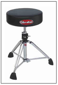
Light weight, compact, sturdy shooing bench
This bench sits on edge, and takes up very little room in the back of the car!
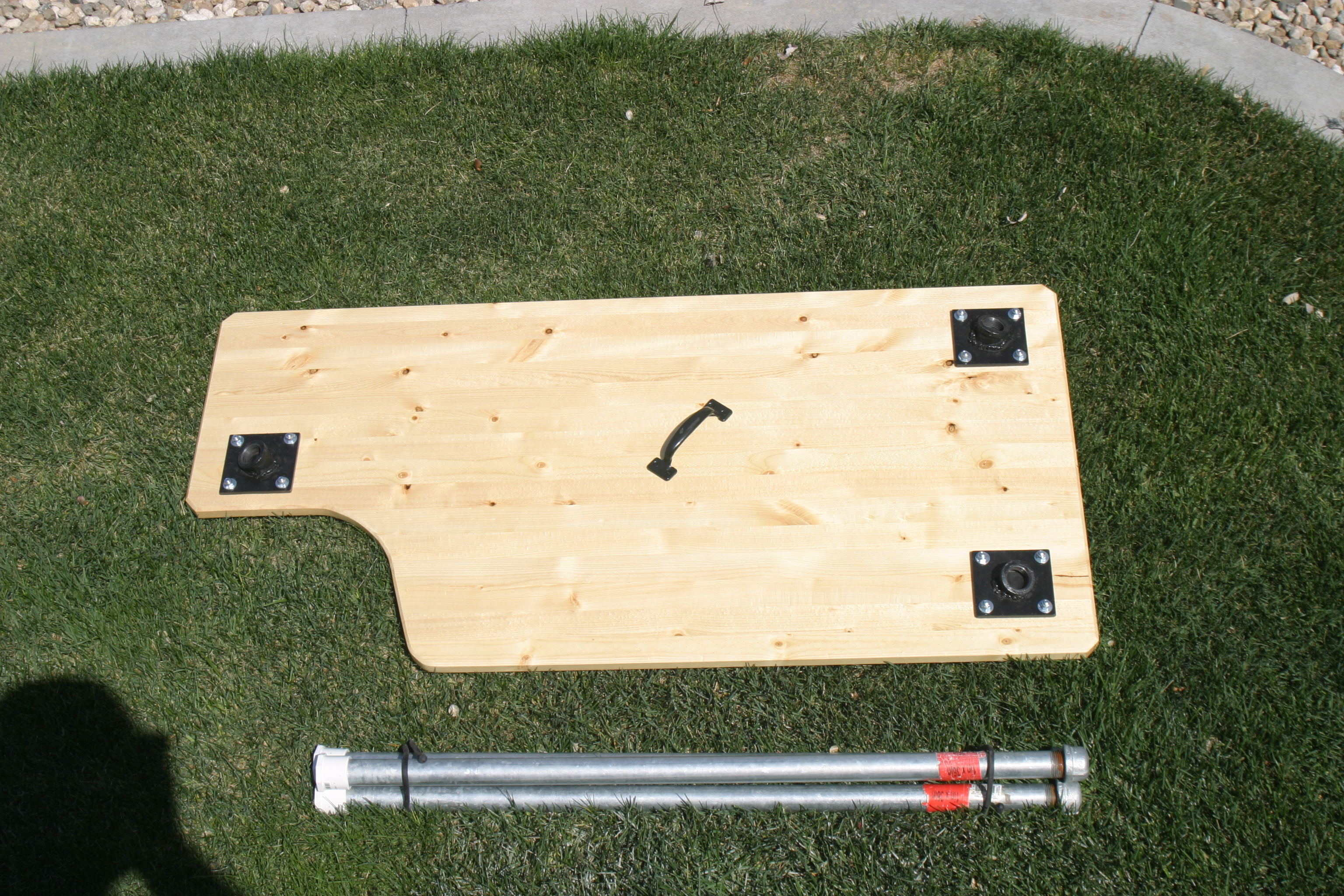
Rear leg is on the bench center line, leg points straight back.

Right front leg attachment. Points out at 45°.
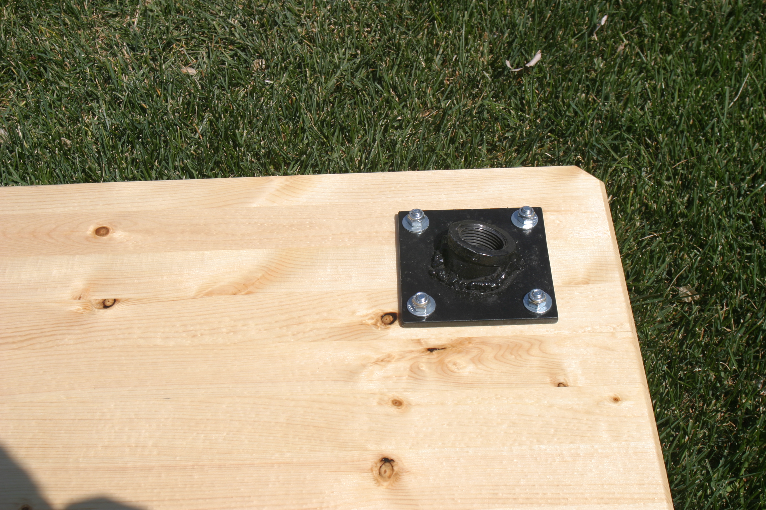
With legs attached you can easily see the angles: 14° and 45°. Leg are 36” long.
Bench setup with Gibraltar drummer’s throne.
I am working on a leg transporter that will secure the legs, and I plan to paint the legs flat black. I’ll make that the subject of another missive.
In case you are wondering, the pockets for the bolt heads have not interfered with either bipod or mechanical rest use.
Here is the drilling template for a simple carrier for the legs. All you need to do is print it out at 1:1 scale, twice, stick it onto two pieces of 3/4" solid wood, and drill the holes as shown, then cut away the scrap, leaving 3 half holes about the center on each piece. Connect the two pieces with a convenient length of something not over 0.870" diameter, so use a 3/4" rod. Place the legs into the cutouts and then tie them up. I use a Niteyes Gear Tie, but anything from shoelaces to pipe clamps will work. Once tied to the carrier, the legs and carrier act as a single unit making it much easier to carry. Add a strap to the carrier and you can go hands free!
Leg carrier in use
Leg carrier detail
NOTES:
Since I built the shooting bench to transport on my UTV, I've
sold
the UTV and bought a Hummer H3 ... and installed a long roof
rack.
The bench with it's legs easily fits inside the roof rack,
along with two or three of the Portable Target Stands (below).
Pictures when I think about it.
While the bench was onboard the UTV over the winter rain caused the leg's threaded segments to rust. I wire brushed the threads put lithium grease on all of the threads. That corrected the rusting problem and made the legs easier to install and remove, but the grease wanted to get all over everything. I put threaded PVC pipe caps on the legs to act as thread protectors and to protect everything else from the grease. So far it's working, just have to keep track of the caps when the bench is deployed.
The concept for this target hanger is that it be inexpensive, easy to build, portable in my UTV, a pickup, or the roof rack of my HUMMER H3, man portable from where ever the closest road is, across broken ground filled with badger holes, sage brush, etc. and that it supports up to a 12"x3/8" AR500 target, and holds up to 308 impacts from 100 yards out with the smaller AR500 targets (maximum energy transfer to the hanger).
The hanger is made from two 10' lengths of 1/2" rebar, a couple inch long pieces of drill rod, a couple of pieces of (pick one; galvanized pipe, plastic pipe, copper pipe) with inside diameter of 1" or preferably just slightly larger. The length of the pipe is not critical. There are two considerations. If the pipe is tight on your rebar you may need to be able to get a good grip on the pipe to futz it around until the legs open or close. If your bends are not tight, a short length of pipe might be able to work its way around the bend and become lost in transit, disabling the target hanger. Should this happen, you can make a field repair with anything from shoe laces to paracord, or duct tape.
When I built the first of these hangers I though it would be easy to heat the rebar to a temperature at which I could bend it by hand. Propane wasn't hot enough. MAPGAS took about 30 minutes to heat to bending. I didn't want to buy acetylene just for this, so I started looking at cold bending and came up with a simple and inexpensive way to do it.
If you do use heat, you can get nice tight bends fairly easily, and without any tools. You will have to pay attention to get the second bend in line with the first bend, and I found it useful to stick a couple of pieces of scrap wood together as a makeshift angle gauge to keep the bends uniform. You'll also have to pay attention if using PVC couplings for the hinges to make sure you don't melt them!
If you are going to cold bend, you need a forged eye-bolt and a 3' or longer piece of pipe large enough to contain the rebar. I used 1" black iron pipe. The eye-bolt needs to be forged to be strong enough to work. Then you need a length of 4x4 or equivalent to mount the bolt. Mine is 3' long. There is a stack of washers (fender then regular) under the nut to distribute the load on the 4x4. The jig can benefit from an accessory clamp to hold the rebar in position, and resist slippage and twisting, or you can do like I did and just use your foot. If you do use your foot (or someone else's foot), really bear down to keep the rebar from slipping. I recommend you make up a 'V Block' that can be clamped tight enough to resist slipping and twisting. Something very similar to a gunsmith's barrel vise. When I get mine done, I'll post an update.
Here's a picture of my current 'bending kit'.
In the future I will recess the eye-bolt washers and nut to get the back of the jig flat, and install a 'V' block clamping arrangement to tightly secure the rebar for bending.
And a closeup of the forged eye-bolt.
Measure and mark the first 10' rebar at 4' from each end. This
will leave a 2' wide top (hanger) run.
Measure and mark the second
10' rebar at 4' 0-1/2" from each end. The second leg's top run
will be 1' 11" leaving just enough clearance for the legs to
fold flat.
Insert the rebar into the eye-bolt and advance it to the bending mark. Slip the bending pipe over the 4' leg and while holding the 4x4 on the ground (stand on it) bend the pipe upward to 80 degrees. As you bend, the standing part of the rebar will want to creep toward the eye-bolt. To get a clean bend you need to prevent that with either your weight (all of it!), or a clamp.
Bend one leg of each piece of rebar, and then remove it from the eye-bolt.
Place the two pieces of rebar together with the bent legs on the same side, and roughly aligned. You could tie the bent legs together using a piece of line somewhere near the foot of the leg, if it helps you control the assembly.
Slip two lengths of whatever pipe you chose to use over the long straight section of both pieces of rebar. The pipes becomes the hinges at this point. Push the pipes to the end with the previously bent legs.
Insert one of the unbent legs into the eye-bolt and clamp it to the 4x4 making sure the bent portion of that leg will be in line with the bend you are about to make.
Bend the 3rd leg to 80 degrees and in the same plane as the opposite leg. Remove the leg from the eye-bolt.
Insert the 4th leg, and as you just did, bend to 80 degrees in the same plane as the opposite leg. Remove the leg from the eye-bolt.
Move the hinge pipes to the outside end of the top run. Unfold the legs to setup the hanger. If everything is working correctly, you are ready to weld chain studs onto the top run.
I use a welding magnet to hold a 1" length of drill rod (sized to fit inside whatever chain I'm using to support the target. In my case 3/16") at 90 degrees (left/right) and parallel to the leg its welded to, so that when folded flat the stud is not sticking up at an odd angle.
Place the chain stud a convenient distance away from the end of the hinge pipe and weld it in place.
NOTE: On the next one I build I'm thinking about drilling a pocket for the chain stud. I'm also thinking of preparing the rebar by grinding off the 'texture' for about 4" toward center from each leg to allow the hinge to rotate easily, and make drilling the stud pocket easier.
Here's what a finished hinge should look like
I have found that looping the chain over the top run once and then dropping a link over the stud is all that's needed to support the target during the most energetic impacts. It may be slightly more stable if you pass the chain from the shooter side over the top, rather than as shown in the next picture. I believe the chain in the picture will go loose in a hit, and wrapped the opposite way it will tighten.
Here's a picture of the completed target hanger.
And some of the targets I use with these hangers.
Targets are AR500 shapes suspended by chain. The bolts are inserted from the front, pass through the chain and have a fender washer an nylock nut to hold the target to the chain loosely. This arrangement cause the target to lean slightly toward the ground which helps with splatter control. Using a grade 6 bolt will slow down splatter erosion, using a carriage style bolt head will do the same.
US Army Aberdeen Proving Ground RDECOM Research Laboratory Technical Report Search Page
Pressure Trace
QuickLoad
Kestrel
Range Finders
All Shooting List Emails ...
Computer Database
Printed Records
DOPE Pages
Loading Manuals (Printed)
Load Recipes (online)
QuickLoad
(software)
Exterior Ballistics Software
Applied Ballistics -
AB Mobile (iOS)
JM Ballistics - jmballistics.com
G7 Ballistics
- http://www.gseven.com/ballistic-program
General Links
Accuracy
and Research Links
Hardware
Links
Return to top