DX View
QSL.net
Propagation
Understanding Propagation
NOAA
Geomagnetic Disturbance Real Time Maps
Dr. Tamitha
Skov
Contact Me:
W7ACP
Welcome to South Western
IDAHO
South Western
Idaho has a very wide range of terrain,
vegetation, wildlife and climate. Here in
Caldwell, we are at the Western end of the
Treasure Valley, formed initially when the
Yellowstone 'hot spot' was located here. As
the Yellowstone caldera has moved (well, the
effect of the caldera moved on the surface - most
likely the hot spot stood still and the Earth's
crust moved over it.), the mountains created by
tectonic action in the collision of the North
American Plate with the Juan DeFuca Plate were
'melted' by the hot spot. The modern day
result is a valley running from the Oregon-Idaho
border toward the Southeast to just North of the
Idaho-Nevada border then turns Northeast toward
the present day location of the Yellowstone hot
spot in Montana. This valley is surrounded
on all sides by the Rocky Mountains or its cut-off
remains in the ancient Owyhee Range. The
valley floor is around 2,400 feet above sea level
(at my location) while the surrounding mountains
and ridges run to about 6,000 ft to the South and
8-9,000 ft to the north. This has created a
very unique weather pattern for the valley, where
storms coming toward us from the West typically,
dry out as they leave the Owyhee's (to our South),
and start precipitation again when they hit the
Rocky's to our North, leaving us with an average
of 11 inches of rain and 8 inches of snow annually
while Idaho City, just a few miles away in the
foothills of the Rocky's receives an average of 27
inches of rain, and McCall, several miles to our
North and well within the Rocky Mountains receives
over 25 inches of rain and a whopping 138 inches
of snow annually. All of that describes how
the Treasure Valley and the Magic Valley are an
agricultural paradise. Lots of water (from
all that mountain snow), long growing seasons, and
when the fates allow, nearly 5 months of
continuous 'perfect' weather. All we need to be a
'destination' would be to have an ocean beach ...
but alas, what we have is called a 'High
Chaparral' where grass, sage brush and the
invasive Russian Thistle (tumble weed)
thrive. Where the land is not in active
farming we have endless tracts of 'BLM' (Bureau of
Land Management) controlled land that is generally
accessible to the public while also available for
ranching and in some places it is home to herds of
wild horses. My wife and I love to take
trips out into the desert (excuse me 'High
Chaparral') to see the sights, smell the smells,
and meet the wild or nearly wild life of the area.
Some photos we
have taken from around the area click here.
Station Equipment
HF Radio & RF Path
Alinco DM-430T Switching 12v 30A
Power supply.
Yaesu FTDX10 HF/50MHz 100W
Hybrid SDR Transceiver
Morgan
Systems M-400X Broadcast Band Filter
3.5-5.4Mhz 200W 50 ohms (www.surgestop.com)
Updated 12/03/2021.
The various wave traps and
other AM BCB filters did not appear to work in
part because I was looking in the wrong
place. FT8 being a 'weak signal'
protocol was not dramatically affected (or so
I thought), and when I was looking for other
signals (mostly SSB) I wasn't finding
them. A big part of the reason was that
I had a lot of additional RFI from local
sources that had not been attenuated and these
sources signatures appeared to be IMD
(repeating equal frequency spacing).
After dealing with those, using the Palomar
RFI KIt (below), the Morgan M-400X was exactly
what was required to clean up the
remainder. The difference was a very
dramatic doubling of the number of FT8 decodes
per period, and noise levels of S6 on 40M, S5
on 30M, S4-5 on 20M, S0.5 on 17M, S0.5 on 15M,
S0.5 on 12M, S1 on 10M and S0.5 on 6M.
The increased ability to scan the band and
observe RTTY and SSB was very dramatic.
There are still discrete RFI signals of both
single frequency and 'fuzzy' throughout the
entire spectrum, some come from one (and only
one) of my two Windows monitors (Scepter 20"),
and as yet undiscovered sources. The
monitor's power cable has 3 turns through a
1/2" Ferrite (Fair-Right V0) which does reduce
much, but not all of the noise from that
source. I think what I'm seeing is a
signal generated within the monitor, and given
the low cost of the monitor plus the low
degree of interference I'm going to call that
a win.
Palomar
Engineers Coax Noise Filter CMNF-500-50GB
<= 38dB rejection of common mode current
1-60Mhz.
Palomar
Yaesu FTDX10 Transceiver RFI Kit 8
RFI/Noise Reduction Filters 3 ea. ring and 5
ea. 1/2" snap on beads.
NOTE: When placing the 1/2"
snap on beads; take two or three turns of
wires through the center then gently close the
bead while watching the receiver, as the
magnetic field couples you will notice the
effect in reduced noise. If you have the
wire length (and diameter) to take more turns
its easy to adjust and test. When
satisfied snap the bead shut. As a
practical matter, try snapping a bead shut and
getting it open again without any wire to see
how it's done, once in place it may be
difficult to determine. In my case, the
Scepter monitor power supplies were creating a
lot of noise, and five turns in each power
lead quieted the noise down to about 5.5dB
(+24.5dB on the FTDX10's waterfall).
NOTE: DC Power leads that came
with the radio are quite long (about
6'). I installed the RFI Torroids with
14 turns through the center, all in the same
direction. All of the ferrite chokes are
installed as close to the radio as is
practical. I installed one of the 1/2 ID
beads on the USB cable (from the computer for
CAT control and audio), I even put a choke on
the CW key line!
MFJ
993B IntelliTuner Automatic Antenna
Tuner.
NOTE: I really like this
tuner! The FTDX10 has an internal tuner
that can do quite wide match, but this tuner
can do so much more it makes it worth
the additional expense. It has made my
intentionally non-resonant 95.375 foot antenna
wire (connected through the Palomar 'Bullet'
9:1 UNUN) functional on 80M through 10M and it
provides a 1:1 match to the radio most of the
time. What it's doing is coupling the
transmitters power into the transmission line,
UNUN and antenna. Very little reflected
power toward the radio. All that power
is either radiated as RF or as heat in the
antenna system. So far it appears to be
radiating RF far more than heat, as I
increased my 'footprint' as seen on PSK
reporter significantly.
MFJ 1708B-SDRS SDR
Receiver TR Switch
NOTE: This switch makes it
possible to run the RSP1a as a spectrum analyzer
looking at the output of the radio. It
also allows the SDR to be used to observe a wide
spectrum of frequencies while operating the
transmitter.
MFJ 1701 6 port Antenna
Switch common through NI4L
HF Choke Line Isolator (CM choke) to reduce
RFI.
SDR Play RSP1a (Software: SDR Uno) connected
through the TR switch to allow receive
operation even when transmitting from the
FTDx10.
MFJ-1026
DELUXE NOISE CANCELING SIGNAL ENHANCER
This device uses a sense
antenna and amplifiers to invert local noise
signals and add them back into the receiver
antenna input during receive. It has a
built in TR switch that apparently MFJ is
not very confident in, but my transceiver
doesn't have a distinct TR output that is
easily accessible, so I'm relying on the
built in. Turns out that on my unit
the T/R Delay must be set to 0 (full CCW)
versus the 10 (full CW) the manual specifies
to allow the TR relay to drop out at
all. Many YouTube videos describe the
operation of this unit, and a few even
discuss the sense antenna, but rarely do
they delve deeply into how it works. I
intend to write up my experience as an
article on this web site, but for now, my
experience is that if you have an end fed
half wave antenna as your main antenna, you
are going to want a similar antenna as a
sense antenna. If you want to use this
device to reduce AM Broadcast Band
interference, it is essentially useless, and
if you want to use it to mitigate left over
local noise it might be possible, but it's
going to be difficult to setup and may need
to be changed as often as you change
bands. At the moment I'm thinking of
removing it, but I put it in front of the
SDR, so I'm might leave it in the circuit
for a bit to investigate using it with the
SDR to create a useful "PANADAPER".
Antennas
Narrowband Antennas
Wolf
River Coils SOTA (Modified) tunable
vertical with ground plane 40M through 20M.
TRAM
1480 VHF/UHF 6db colinear 5/8 wave,
mounted atop 8' of black steel 'fence top
rail'. Connected directly to BTECH
UV-25X2.
HamStick antennas; 75, 40, 20,
15, 10 meter.
Uncategorized Antenna
Equipment
Jackite 31
ft telescoping fiberglass kite pole (good for
field day; getting a lightweight wire up, or general
stuff; pushing a network cable under).
Retired Antennas
Retired:
Alpha Antenna JPole Jr. 34'
End fed 'sloper' feed end at 30' AGL (Above
Ground Level) sloping to 10' AGL fed at
the North end with the wire sloping to the
South, so East/West should be strongest
signals, you would think, but read on!
VHF/UHF Radio & RF Path
Computer & Data Path
Mac Mini -
My office workhorse; produces the secure (LetsEncrypt) Internet
presence for this web site, (Apache HTTP Server)
publishes several MySQL
databases, handles all storage, video, html
editing, email, etc.
Retired: Acer Notebook -
configured primarily for Application
Generation with AppGini for MySQL databases.
Retired: Toshiba Satellite
Notebook - configured primarily for Radio
Control with DxLabs, WSJT, and other radio
control software.
Test Equipment
Fluke 77 DVM (circa 1970, my old
friend!)
NANO VNA Network Vector
Analyzer
Looking for an inexpensive 100
Mhz dual trace storage oscilloscope. Thinking
about YEAPOOK ADS1014D among
others.
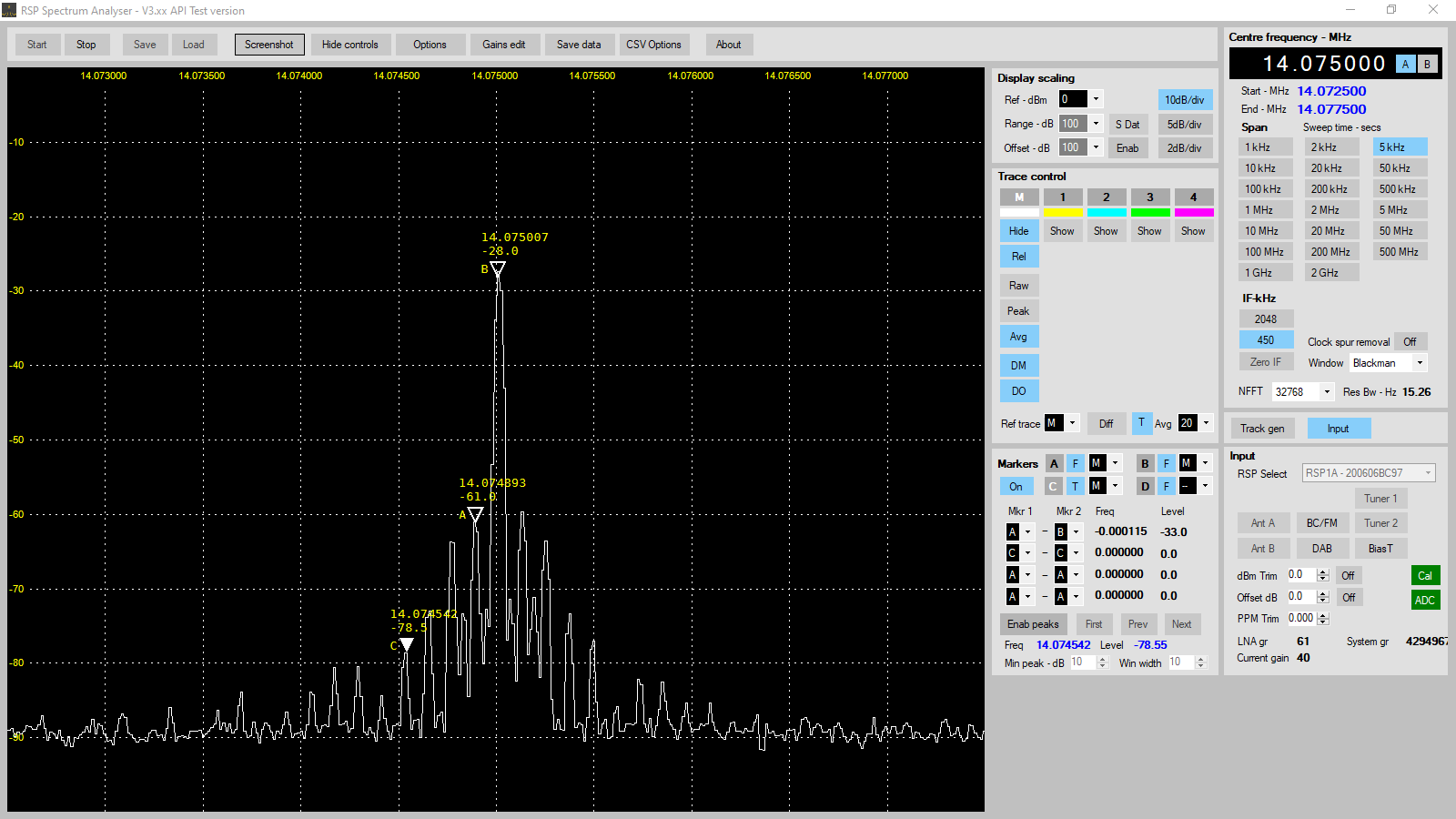
NOTE: The RSP1a SDR makes a fine
spectrum analyzer to sample transmitted
signal. My current antenna is selected by
a switch box, then routed through the MFJ 1708B
SDR TR Switch to the RSP1a and the Yeasu FT10Dx
transceiver. When in transmit there is
just enough RF energy still present to provide
the RSP1a with a very usable sample. Good
way to check for modulation and spurious
emission (my first harmonic is less than 30 db
down - GOOD!) Tuning my audio card volume
and WSJT-X's power control shows that for FT8
mode I can run the selected audio card at full
volume, and the program power level at 100%
without distortion and that I do not have to
apply any wave shaping to produce a clean
transmit signal.
20210730 I captured this screen
shot from the Spectrum Analyzer app running on
the RSP1a. Conditions: WSJT-x FT8 Tune
mode with transmit frequency set to 1000 Hz,
Power 100%, into Palomar 55 antenna, sampled by
RSP1a inline via MFJ 1708B. First harmonic
is -33db 4th harmonic is -50.5db. The
signal is averaged over 20 sweeps.
Yeapook ADS1014D
Oscilloscope
Software
Skimmer (not until it
works with my SDR or another inexpensive
one). Skimmer is expensive - but it could
be worth it since there are few reverse beacons
near me. But not until I have a proven
antenna system ...
DXLabs - Best radio
control, DX, Contesting software, but it needs a
native CW decoder!
NOTE: Replaced DXLabs with Ham Radio
Deluxe. I'm anxiously awaiting Dr.
Carpenter's update to this software to display
the radio control as an image of my Yaesu
FTDx10. In the mean time, I have updated
its database to MySQL, with Apache and PHP on
the AWOW computer. It works adequately
fast even when Grid Tracker 2 is running in
conjunction with one or two Edge (web browser)
tabs open to PSK Reporter, QRZ and LOtW.
If I open more tabs, the computer starts to run
into CPU utilization slowdowns.
WSJT - The best way to
'do' FT-8 etc.
JTAlert - Adds serious
functionality to WSJTx for things like 'worked
before' and 'Calling You'.
NOTE: As of July 2021 I have
configured WSJTx and JTAlert to cooperate and
control FT8, logging (both local and LoTW) and
spotting. Working on how to automatically
and timely update LotW and QRZ logs.
PSKReporter
CWGet - Works off
the sound card, so it can work with DXLabs
Winwarbler.
CHIRP - Allows programming
HT's to the same channel (frequency) etc. even
if they are different model numbers from
different manufacturers. But its a bit 'clunky'
- I may have a look at creating the same
functionality using some other tools and
database(s).
|
Project List
Antenna Analysis
VNA analysis of my
antennas - or - Learning how to use VNA Windows
software.
4NEC2 modeling and analysis of antennas and antenna
design ideas.
Antenna
Install and Test
- Using a 30' flag pole to
'fly' a wire antenna and stay under the radar
(maybe).
As well as how well it works, and how much
sensitivity it has to installation direction.
NOTE: This project is mostly complete. The
Palomar 'Bullet' and 95.375 ft #14 THHN wire
antenna is designated antenna 'P95'.
- Using two 17M 'Hamstick'
antennas to form a vertical dipole, model and
test.
- If this works as I think it
will, these should make an ok DX antenna.
- Based on results, construct
a self supporting, vertical half wave 40M
antenna, then add additional vertical half wave
antennas to the structure to create a multi-band
40M-10M antenna with low radiation angle.
- Cut for FT8 operation,
these are the half wave antenna lengths:
- 40M 66.00'
- 30M 46.12'
- 20M 33.22'
- 17M 25.83'
- 15M 22.18'
- 12M 18.75'
- 10M 16.65'
- 4Nec2
Analysis HamStick
- 4Nec2
Analysis VDipole
- Relative ERP map by
skimmer/beacon.
Comparison to Wolf SOTA vertical
and other antennas.
Transact (or something) the DXLabs and WSJTx MS Access
log databases on JWIN into MySQL tables on JMAC so I
can archive, and manipulate, display etc. outside of
the applications. See if AppGini can ingest
'em? Otherwise use Open Office Db to enumerate
and export?
One Click Reports I want to write:
- List today's QSO's by time.
- List today's QSO's by band
and distance.
- List states & countries
QSO'd today.
- List outstanding QSL's.
- List QSL's by date/time.
Shack
Grounding
- Ground rod installed &
connected - working on eliminating noise and KCID
AM before I write it all up. The ground rod
is connected to a 'loom' which is usually found
inside an AC distribution panel, but in this case
is screwed directly to the wall behind the
desk. There are 9 positions, one ground
wire/equipment per. Currently using 1 for
the ground rod, and 4 for equipment grounds.
- I have found a bit of a
difference in potential between the 3rd wire
ground and the ground rod. I've made up a
jumper and plug that allows me to easily bond the
two grounds for testing and evaluation. So
far I have found no significant effect one way or
the other.
- Pending:
- Lightning Ground
- Signal Ground
- EMI Ground and Shielding
(I've got a great large (1490Khz/1KW) KCID AM
ground wave transmitter 500 yards to my
East). Working with Palomar Engineering to
get the RF (both mine and KCID's) on the coax
shield stopped before it gets to the radio using
filters and chokes.
Radio Continuity of Operation
- New battery for UPS
- Power OP strip from UPS
(JMac & display, JWin & displays, ext
drives, HF, VHF & UHF radios, HT charger.
- New automotive/deep cycle
battery for transmitter(s)
- Solar charger.
- Recharge all radio and
UPS batteries.
- Switch radio over from
commercial to battery. Temporary immediate
phone, CW only.
- Generator
- Switch house (RV) and
entire shack to generator (change 50A and 30A
source from commercial to genset), consider
FrostKing heat tapes etc. Temporary all modes.
Reduce QRM on 160, 80, 11, 10
meter bands due to KCID and general noise.
DMR Digital Mode Radio
ICOM ID-51 Docs
Delta
Loop Antenna(s)
Completed Projects
|